• Steel Soldiers now has a few new forums, read more about it at: New Munitions Forums!

  • Microsoft MSN, Live, Hotmail, Outlook email users may not be receiving emails. We are working to resolve this issue. Please add support@steelsoldiers.com to your trusted contacts.

Looking for V100 chassis pics

M813rc

Well-known member
Steel Soldiers Supporter
4,182
3,091
113
Location
Near Austin, Texas
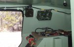
Most of the intercom cables run along under the roof line and are rather loosely draped. They are held up by loops that bolt to threaded posts welded to the hull.

The single cable going forward runs along the right side, from the main intercom control box (AM-1780) above the radios to the right front "shotgun" control box.
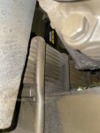
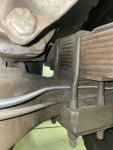
On some V100s, this cable runs under the roof line, however many (including mine) route the cable down under the side seat and up the corner of the forward wheel well/hull line to the control box.

Another cable runs from the passenger box across the front of the roof beam to the driver's side box.

A cable runs back under the roof from the AM-1780 to the rear position. That intercom box can either be on the rear hull wall (as in mine) or on the back of the wheel well. The coaxial cable from the right rear antenna also runs along with this intercom cable.

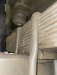
The power cable for the radio system comes out of the top of the engine bay wall and goes across the roof and straight down the wall to brackets welded to the hull wall, behind the radios.

There is a square speaker mounted to the hull wall to the left of the AM-1780, another on the hull wall by the driver and passenger.

Captions on pictures explain what they are. A couple were taken in a different V100.

Cheers


Radio area (not my V100).jpg radio area.JPG Passenger side.jpg cable from passenger side.jpg drivers side.jpg rear position - 1.jpg Rear position.jpg Rear position - 2.jpg V100 m706 int.jpg Speakers LS-454-U.jpg
 

Attachments

Last edited:

M813rc

Well-known member
Steel Soldiers Supporter
4,182
3,091
113
Location
Near Austin, Texas
I neglected to mention this - the top hatches are spring loaded to assist in opening/closing them, mostly closing.
In the open position, the hatches are held in place by a heavy clip that keeps them from moving/bouncing.
Each of these has a mechanism for releasing the catch from inside the hull, so they can be closed when coming under enemy fire without having to reach outside. You grab the knob and pull down firmly. Once released the hatch will swing over to the closed position. You do NOT want your fingers or any other body part in the way when that happens!

Cheers

drivers side hatch release knob.jpg
 

Paweł

Active member
45
124
33
Location
Poland
Hello Rory!
Thanks a lot for the interesting info! Now I've hot the commo wiring sorted out, I'm working on rendering that in scale. I've seen that mysterious knob on some photos before, but I kinda forgot about it. After what you wrote me in your last post I have to have them on my model! Thanks again and have a nice day!
Paweł
 

Paweł

Active member
45
124
33
Location
Poland
Hello everybody!
I’ve had a vacation break, but now that it’s over I’m moving on with this build. I’ve finally equipped the upper hull - there was mainly the AN/VIC-1 interkom, a first aid kit, a flashlight and some more minor details there. Here’s how it looks like now:
1:35 M706 Commando by Pawel

1:35 M706 Commando by Pawel

Now I will close up the hull and try to fill and sand all the joints smooth, then I’ll add some more details to the interior and move on to the suspension.
Thanks for looking and have a nice day
Paweł
 

Buck Wampum

Active member
Steel Soldiers Supporter
64
131
33
Location
SE PA
Very impressive level of detail. Is this an E2 version of the V-100? I’m assuming yes, based on the square opening in the roof. If you’re going to put a turret on it, no one‘s going to get to see all that great detail!
 

Paweł

Active member
45
124
33
Location
Poland
Very impressive level of detail. Is this an E2 version of the V-100? I’m assuming yes, based on the square opening in the roof. If you’re going to put a turret on it, no one‘s going to get to see all that great detail!
Buck - thanks a lot for your comment! You're right, I'm building my model as the E2/USAF version, mostly because I've found a Vietnam veteran who operated one back then and is kind enough to help me with my research, wasting such opportunity would feel really bad! Maybe, if this project goes well, I'll try to build another one, this time an Army one with a turret.

Rory - thanks a lot! Did you notice the fire extinguisher handle and the hatch releases? I wouldn't know them if you didn't help me - thanks a lot for that!

I hope to have another update soon - thanks for looking and have a nice day

Paweł
 

Paweł

Active member
45
124
33
Location
Poland
Hello everybody!
I have closed up the hull. Wanted to show you how much of the interior will be visible:
1:35 M706 Commando by Pawel

1:35 M706 Commando by Pawel

I have cut off a piece of hull because it prevented me from installing the radios. Now I have to glue it back and smooth out everything, I also want to add some missing welds.
1:35 M706 Commando by Pawel

I also have the benches left to be installed. As per tip from ikar01 (Bob) the benches will be folded up, to make a room for a place to sleep (on top of the ammo boxes on the floor).
1:35 M706 Commando by Pawel

I also filled and sanded the underside. Soon I will be able to start all the fun with the suspension!
Thanks for reading and have a nice day!
Paweł
 

M813rc

Well-known member
Steel Soldiers Supporter
4,182
3,091
113
Location
Near Austin, Texas
Rory - thanks a lot! Did you notice the fire extinguisher handle and the hatch releases? I wouldn't know them if you didn't help me - thanks a lot for that!
I did, and am amazed at how real you are making all this look. Most impressive work indeed! I'm very glad to have helped in any way.

Cheers
 

Buck Wampum

Active member
Steel Soldiers Supporter
64
131
33
Location
SE PA
Buck - thanks a lot for your comment! You're right, I'm building my model as the E2/USAF version, mostly because I've found a Vietnam veteran who operated one back then and is kind enough to help me with my research, wasting such opportunity would feel really bad! Maybe, if this project goes well, I'll try to build another one, this time an Army one with a turret.

Rory - thanks a lot! Did you notice the fire extinguisher handle and the hatch releases? I wouldn't know them if you didn't help me - thanks a lot for that!

I hope to have another update soon - thanks for looking and have a nice day

Paweł
Are you going to install the spring loaded fold down jump seats by the side doors? I think those were an E2-only option. Really wish they had those on all of the V100s, they’re very handy for facilitating easy entry/exit via the side door.
 

Paweł

Active member
45
124
33
Location
Poland
Hello!

@Buck Wampum - like Rory said, I have the jump seats there:

1725641554547.png

And I have everything nice and smooth now:

1:35 M706 Commando by Pawel


1:35 M706 Commando by Pawel

As you can see I added some lugs on the rear - where the fuel can holder and pioneer tool rack would bolt to, but USAF didn't seem to use them - I guess on the airbase they would only add weight here. I have also added some missing welds on the sides. And now I can start working on the suspension.

So first I had to work on the springs. OOB they look like this:

1:35 M706 Commando by Pawel


1:35 M706 Commando by Pawel


And here are my tweaks:


1:35 M706 Commando by Pawel


Now I have to build new shock absorbers and their mounts, and also the bolts attaching the axles to the springs. FUN!


Thanks for looking and have a nice day


Paweł
 

M813rc

Well-known member
Steel Soldiers Supporter
4,182
3,091
113
Location
Near Austin, Texas
Absolutely splendid attention to the details! I'm really enjoying watching you build this.

Having seen how much effort you are putting into this, are you going to rework the grill over the exhausts? (That big scoop on the back of the hull).

Cheers
 

Paweł

Active member
45
124
33
Location
Poland
Hello Rory!
Thanks a lot for your comment!
Somehow I didn't quite look at this detail yet - I'm focusing on the underside, but can you tell me what needs reworking there?
I also have the last (fixed) fire extinguisher done - it's just a little hard to photograph...
Thanks in advance for your help and have a nice day!
Paweł
 

M813rc

Well-known member
Steel Soldiers Supporter
4,182
3,091
113
Location
Near Austin, Texas
The grill that comes with the kit is for a V150, and has the upper extension with the exhausts through it. The grill itself is solid.

Going through my photo files and references, I did not find any USAF M706E2s with the exhaust pipes coming through the upper extension.
I don't recall seeing that type on E1 style Vs either, but I didn't go through my files on those.

The upper extension is present on some E2s, absent on others, so the choice there is yours.
Photos show that the grill arrangement is the same as on my V. My V does not have that upper extension.

The attached photos should show everything. The grill sits on tabs welded to the inside of the "scoop" and is held on with bolts. The two mufflers (silencers) are bolted to tabs welded to the scoop wall.

Cheers

7 - Copy.jpg 1 - Copy.jpg 2 - Copy.jpg 3 - Copy.jpg 4 - Copy - Copy.jpg 5 - Copy.jpg6 - Copy.jpg 8.jpg 9.jpg 10.jpg
 

Buck Wampum

Active member
Steel Soldiers Supporter
64
131
33
Location
SE PA
One of my V100s has the fording shroud and the other does not. Either way, the grate over the exhaust bay is the same for both vehicles. Here’s pics of the one with the fording shroud. Ignore the lights, those I installed because I drive my vehicle on the street and they’re required. No idea if the exhaust tips sticking through the shroud are correct or not not. Best bet is to rely on Vietnam pictures.

IMG_7714.jpegIMG_7715.jpeg
 

Buck Wampum

Active member
Steel Soldiers Supporter
64
131
33
Location
SE PA
And here is another V-100 with a fording shroud that is at a museum in New Jersey. Same holes for the exhaust system. The large cylinder on the back of the vehicle was for a fire extinguisher/suppression system, from its days as a police riot vehicle.

Both of these vehicles (mine and the one at the museum in NJ) went through arsenal rebuild after the war, one (mine) at Tooele Army Depot (TEAD) in Utah and one (the NJ vehicle) at Letterkenny Army Depot in Pennsylvania (LEAD). It’s entirely possible the shrouds were added there during the postwar rebuild
 

Attachments

Paweł

Active member
45
124
33
Location
Poland
Rory, Buck - thanks a lot for your comments and for the great pictures you posted. There are not so many photos on the 'net showing this - because normally you have to climb on a ladder or something like that to photograph it! Now this won't be easy... As the kit doesn't show the insides of the scoop right, especially the surface where the fan should be is quite different - it doesn't make much sense to make the grating see-through. The fins would have to be pretty thin in scale, too... I'm thinking about making a 3D printed part with thin fins and deep slots between them (but not going all the way through - this way the part can be stronger).

I've just finished putting together the rear suspension - I'll post some photos soon.

I wanted to ask you one thing about the front suspension - I have a feeling there is some kind of wedge between the front axle and the front springs, is that right? Could you please post some photos of the place where the front axle is bolted to the front spring?

Thanks in advance and have a nice day

Paweł
 

M813rc

Well-known member
Steel Soldiers Supporter
4,182
3,091
113
Location
Near Austin, Texas
I agree that doing all that work for something that will likely be invisible is not necessary, and your idea of deep slots will look fine.

I'm away on a trip at the moment, and won't have access to my photo files until early next week. Perhaps Buck can provide the front axle information in the meantime.

Cheers
 

Buck Wampum

Active member
Steel Soldiers Supporter
64
131
33
Location
SE PA
In the first attachment, the drawing from the – 24P parts manual, that is the left front spring, with the left side of the drawing being in the front of the vehicle. As a further reference, he retaining nut for the Lower end of the shock absorber faces the rear of the vehicle.
 

Attachments

Top
AdBlock Detected

We get it, advertisements are annoying!

Sure, ad-blocking software does a great job at blocking ads, but it also blocks useful features of our website like our supporting vendors. Their ads help keep Steel Soldiers going. Please consider disabling your ad blockers for the site. Thanks!

I've Disabled AdBlock
No Thanks