• Steel Soldiers now has a few new forums, read more about it at: New Munitions Forums!

  • Microsoft MSN, Live, Hotmail, Outlook email users may not be receiving emails. We are working to resolve this issue. Please add support@steelsoldiers.com to your trusted contacts.

MEP-804A turns over but won't start (governor module?)

crmorse

New member
11
1
3
Location
Alabama
I have a similar but different starting problem from the other 804A start problem threads. I've read everything in those threads and I think I've done all of those tests (details below) so I "guess" I'm down to the governor module being the problem but I want to be sure first before just throwing parts at it.

Background: I've had my set about 5 years but only used it a handful of times during storm outages. I ran test cycles every few months but not super religiously. The only thing I noticed was that it was originally very quick to start--only a couple of seconds to catch and then come up to speed-- and then progressively slower to start requiring me to hold the start switch for longer and longer each time. The last time it started and ran correctly I had to hold it in start for maybe 20 seconds.

Current state: Batteries have been recharged and it will turn over at full speed but does not fire at all. Sometimes there is a small amount of unburnt fuel smoke when attempting to start but it's not very much, nothing like it did when it started.

I do have the TMs and have read them backwards and forward until I'm now blind to what must surely be obvious. Details below but I I think I've narrowed it down to either the governor module not outputting the correct control signal or the governor actuator not reacting to it.

Troubleshooting steps I've taken so far:
* Fuel tank - the last time it ran I nearly emptied the tank but did not run out. I've since filled it full ( which results in the priming pump not running in the "prime' position which was my first "goose chase." I've confirmed the fuel pump runs and when cranking over there is fuel to the injection pump
* Injection pump & prime - I've checked that fuel is flowing to each injector and bleed the system
* governor actuator - I've checked that the throttle solenoid has the right impedance, it works and responds correctly to voltage/current
* MPU - checked & reseated. It is outputting the correct voltage (I've even verified hte signal on an oscilloscope)
* wiring - I did find a mouse nest but could not find any damaged wires. I've checked continuity on all of the circuited relating to start
* start switch (S1) - I've tested that all the circuits make according to the schematic on page 817 (ARMY TM 9-6115-643-24)
* governor module (Woodward 8270-1002) - I've checked the DC voltage in and MPU signal into the module and continuity to the governor actuator. HOWEVER, I have NOT been able to confirm what the module should be outputting to the governor actuator so that's unknown

Known Good:
The engine did fire up immediately when I manually set the throttle position so I know the engine, fuel, and fuel pumps are good, it's most likely a problem in (or before) the governor actuator.

New mistakes:
1. When I tested the S1 I carefully labeled the wires and thought I put them back correctly but now the hour meter runs anytime the dead crank switch is in Normal so I obviously got something wrong. I have not been able to find the page in the TM that lists the correct wire numbers and positions. I need to fix this before I move on troubleshooting.

Special notes:
1. The Woodward Governor module already had all the wires numbered when I started so somebody has been in here before. But it worked when I got it so I don't immediately suspect that.
2. The fuse mod is present.
3. I've seen mentions about another mod (MOV? I don't remember) but I don't know what that is or if I need it.
4. Once I have it working again I want to do the single-phase conversion and add kloppk's remote start kit. This will be the standby generator for my off-grid solar setup
5. Set has 803 hours on it so far, about 30 of those are mine.

Ask:
1. Can anybody point me at the right wire numbers for the S1 switch?
2. What do I troubleshoot next?
3. Is it time to try replacing the governor module? If so, what caused it to fail? Since this is obviously at least the 2nd module in it is it possible that something else is wrong that's burning up the governor modules?

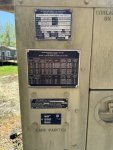
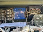
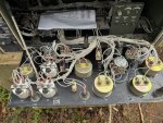
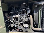
Images of placards, front cover, and engine bay attached.

Thanks in advance!
 

Attachments

crmorse

New member
11
1
3
Location
Alabama
I finally found the wire numbers tonight. They are in "Figure 8. Control Box Harness Assembly" of TM-9-6115-643-24P. Posting here in case it's every helpful for anyone else.

The Master Switch (aka Start Switch) is known as S1 in the schematics. Terminals 2-4-6-8 are all jumpered together on the switch with bus part. The correct wire mappings are:
1 = 172A20
2 = na
3 = 129B20
4 = 180F20
5 = 173A20
6 = na
7 = 190A20
8 = 180D20

I'm still working on what to troubleshoot next.... going through the main TM I thought I found it with a minimum idle set adjustment but that's only for the 804B and I have an A....
 

kloppk

Well-known member
Steel Soldiers Supporter
2,111
3,464
113
Location
Pepperell, Massachusetts
You do NOT need the MOV update. That only applies to the MEP-802A & MEP-803A.

From my limited experience with the Governor Controller module you need the following signal to it in order for it to send power to the mechanical actuator on the engine while cranking.
1) 24 volts DC power across terminals 3 & 4
2) 24 volts DC on terminal 1 for 60 Hz operation
3) Working Frequency adjust potentiometer. Set to midpoint and verify resistance. Disconnect it's wires from the Electronic actuator before checking resistances. 5K ohms across its outer terminals and 2.5K from center terminal to the two outer terminals. Reconnect wires.
4) 24 volts DC to terminal 5 which comes from the overspeed relay coil
5) Correct AC voltage from MPU to terminals 16 & 17.

When those conditions met the Electronic Actuator module should be applying 16-17 volts DC to the mechanical actuator to allow fuel flow.
 

jamawieb

Well-known member
1,432
543
113
Location
Ripley/TN
Ive had several issues out of the governor controls. Kloppk (Kurt) has fixed one of my boards recently.
1st. Test the mpu at the controller. Take number 16 and 17 off. Put you multimeter on ac and measure while starting. Should be around 3v. I had one unit that was loosing continuity and had a no start due to the wire.
2nd test dc voltage on number 3 with the master switch to Prime and run. If thats good. Move to 3
3rd test dc voltage at number 9 while starting. Should be around 20v or less.
Ive been having 2 units that work unit they have sit for 2 weeks or more. I will get it to crank but no start. I can test voltage at 9 and negative on 4. Then it will magically start. Still trying to figure this one out.
 

jamawieb

Well-known member
1,432
543
113
Location
Ripley/TN
Kloppk beat me to it. Lol!
The other big issue Ive encountered with the 804a is the main fuel hose from the tank to the injector pump. It will degrade and actually leak air. Its the weirdest thing. It will not weep fuel. Ive had 12 or more with this issue. You need to take the hose off. Put your finger over 1 end then put alittle fuel (I use carb cleaner) in the other and then blow compressed air in the end you just put fuel in. When you blow air in the hose will weep fuel in the places that are bad. Take it to any place that makes hydraulic lines and get a new one made.
My only theory is that since the 804a doesnt have an electronic pump to force fuel to the pump and the injector pump doesnt make enough pressure for the fuel to weep because it doesnt stay in the line.

The more I think about it, I would test this theory 1st. Especially since it was a good running unit.

Also it looks like you have the original water seperator on the unit and since you dont run it much are you sure it hasnt developed algea in the fuel?
 

crmorse

New member
11
1
3
Location
Alabama
Thank you both for you inputs! I definitely got a result.

1st I fixed the wires on the switch. Only one was in the wrong place and everything acts normal again so that was easy.

2nd I checked all the things ya'll suggested

from @kloppk
1) 24 volts DC power across terminals 3 & 4 ===> CHECK, 24.2Vdc
2) 24 volts DC on terminal 1 for 60 Hz operation ===> CHECK, 24.2Vdc
3) Working Frequency adjust potentiometer. ===> CHECK, 5K ohms across and 2.5K from center terminal to the two outer terminals. Nice clean sweep without any jumps or breaks
4) 24 volts DC to terminal 5 which comes from the overspeed relay coil ===> CHECK, 24.2Vdc
5) Correct AC voltage from MPU to terminals 16 & 17. ===> CHECK
- it was out of range (1v) originally but I was able to adjust it to 3v. I'm sure this was from earlier troubleshooting and not the original problem
- impedance to MPU is good (800ohm)

from @jamawieb
3rd test dc voltage at number 9 while starting. Should be around 20v or less. ===> FAIL, Voltage is 0V <--I'm guessing this is the problem

@jamawieb I'll check out the fuel lines and separator but I don't think that is it based on it's been running perfectly up until now and it will fire up *instantly* if I manually set the throttle. But I will keep it mind and check it for future issues.

Unless anybody else has any ideas I think it's time to change the governor module.
 

crmorse

New member
11
1
3
Location
Alabama
I pulled the governor module today. No signs anywhere of any damage or burned components. The conformal coating has obviously been messed with by somebody before me but no signs of damage anywhere. I'm just waiting on a reply from mc/mac now to buy a replacement.
 

crmorse

New member
11
1
3
Location
Alabama
Several days with no reply from mac/mc so I don't know if he's traveling or what. Does anybody else have a source for a replacement Woodward 8270-1002 Governor Module? @kloppk maybe?
 

crmorse

New member
11
1
3
Location
Alabama
So far I've been unable to find a replacement part. Based on what @kloppk said above and a lot of pictures online it seems like the output FETs burn up often. I've replaced those but I'm still not getting output.

@kloppk When you fixed the one was there anything wrong other than the FETs?

Does anyone know of any schematics available for these?
 

kloppk

Well-known member
Steel Soldiers Supporter
2,111
3,464
113
Location
Pepperell, Massachusetts
@kloppk When you fixed the one was there anything wrong other than the FETs?
The one I repaired looked like this. Vaporized righthand component and burned out PCB trace.

1715881723420.png

I shot gunned it and replaced all 5 components in the row and repaired the burned out trace. The parts didn't cost much.
It passed my quick bench test. Shipped it back to the owner. He installed it in an 804 and it worked great.

1715881689339.png

edit: I did notice the metal tabs of the components were REALLY close to each other, almost touching. Poor design.
 
Last edited:

jamawieb

Well-known member
1,432
543
113
Location
Ripley/TN
Not that I have found. The original model has several variations depending on the exact genset they are used it and they were produced by a few different companies over the years.
This post from the TM section lists some cross-reference numbers
Have you asked Kloppk if you could send in your board for diagnosising? He maybe be able to fix it. No guarantees but worth a try
 

crmorse

New member
11
1
3
Location
Alabama
We did talk. He was very helpful. I ended up deciding to do what he did and just replace all the chips in the top-corner. I'm actually installing it today to find out if that worked.
 

crmorse

New member
11
1
3
Location
Alabama
Well, that went poorly.

1. I reinstalled my original GCU after replacing all of the major components. Exactly the same behavior.

2. To assure myself that the engine would start I connected a variable DC power supply to the throttle solenoid and was able to get the engine to start and run, I just didn't have enough control to actually be able use it this way (no surprise).

3. I gave up on this GCU and bought one I found on eBay. It arrived and I installed it being careful to double-check every wire number since some of the hand numbered marks on the crimp connectors from whomever did this before me are a little vague now.

4. Replacement GCU does not turn over the engine at all. I can hear a large solenoid click that sounds like the starter solenoid but no rotation at all. Not even a tiny bit as if the engine was locked up. The Dead crank switch spins the engine very fast. Following the GCU adjustment guide I checked the voltage at the input and the two solenoid outputs and everything matches spec.

I'm at a complete loss of what to do next. The only difference between the original and replacement GCUs I can see is mine is a "Rev C" and the replacement is a "Rev D." The seller listed it as tested and verified working but I don't know if that's actually true or not.

Any ideas what to do next?
 

Guyfang

Moderator
Staff member
Moderator
16,494
23,483
113
Location
Burgkunstadt, Germany
You wrote:

Well, that went poorly.

1. I reinstalled my original GCU after replacing all of the major components. Exactly the same behavior.

2. To assure myself that the engine would start I connected a variable DC power supply to the throttle solenoid and was able to get the engine to start and run, I just didn't have enough control to actually be able use it this way (no surprise). (You can hot wire the Actuator, and it starts, then install an A5 (GCU) that you just tossed in some parts, in the hope that it might fix the problem. This is not troubleshooting. You still have no idea if the A5 is good or not.)

3. I gave up on this GCU and bought one I found on eBay. It arrived and I installed it being careful to double-check every wire number since some of the hand numbered marks on the crimp connectors from whomever did this before me are a little vague now. (Never use the numbers someone writes on the crimp connectors. Look at the numbers on the wires. The wire numbers are 100% right. )

4. Replacement GCU does not turn over the engine at all. I can hear a large solenoid click that sounds like the starter solenoid but no rotation at all. Not even a tiny bit as if the engine was locked up. The Dead crank switch spins the engine very fast. Following the GCU adjustment guide I checked the voltage at the input and the two solenoid outputs and everything matches spec. (What is the part number on the "New" GCU? Is it the same exact part number as the old GCU? AND, is the part number the same as in the parts TM?)

I'm at a complete loss of what to do next. The only difference between the original and replacement GCUs I can see is mine is a "Rev C" and the replacement is a "Rev D." The seller listed it as tested and verified working but I don't know if that's actually true or not.

How many volts do you get at the female end of the A6 plug, when you turn the S1 to the start position?
Were there any fault lights on when you tried to start it other that low oil pressure?.

1727712128193.png

Looking at the A5, if you hooked up the Crank disconnect switch wrong, then the Starter would NOT engage. The engine DID turn over with the "old" A5, both before and after you "Fixed" it. If you just put in a "new" A5 and the engine will not turn over, then that problem just might be how you wired it up. So please do not just look at someone else's markings on the ring connectors.

Also, if you hooked up the Overspeed wire, 155A in the wrong place, the engine will NOT start.
 

crmorse

New member
11
1
3
Location
Alabama
(You can hot wire the Actuator, and it starts, then install an A5 (GCU) that you just tossed in some parts, in the hope that it might fix the problem. This is not troubleshooting. You still have no idea if the A5 is good or not.)
This is true. I have been unable to find a schematic for the GCU so all that was left is following traces and testing components. Everything that we (my brother is a radar EET and has been helping) could test and measure checked out. Without schematics to actually know what everything should be we hit a wall. I have previously tested all of the inputs (results in thread above) and all of the outputs on the original GCU and the only thing wrong was 0V on 9 & 10.

(Never use the numbers someone writes on the crimp connectors. Look at the numbers on the wires. The wire numbers are 100% right. )
Roger that. I apologize, I guess my wording before was clumsy. That is exactly what I have done. All wires numbers have been cross-checked with the TM and the attached sheet and verified as in the right place. I did not at any point have any wires in the wrong place.

(What is the part number on the "New" GCU? Is it the same exact part number as the old GCU? AND, is the part number the same as in the parts TM?)
Differences in BOLD & UNDERLINED
Mine:
Woodward
CAGE: 31361
P/N: 8270-1002
Rev: C
SN: 17732743

Replacement:
Woodward
CAGE: 31361
P/N: 8270-1002
Rev: D
SN: 18710469

How many volts do you get at the female end of the A6 plug, when you turn the S1 to the start position?
Were there any fault lights on when you tried to start it other that low oil pressure?.
I have not investigated A6 yet. I will do that next. So far for troubleshooting I have been using the doc you linked below (that's the one I tried to link for the other poster earlier in this thread but messed up).

I get ~24V at 3 & 4 ONLY when S-1 is in START position.
I got ~21V at 19 & 18 as per the instructions but starter lock out never happens since the engine never starts


Looking at the A5, if you hooked up the Crank disconnect switch wrong, then the Starter would NOT engage. The engine DID turn over with the "old" A5, both before and after you "Fixed" it. If you just put in a "new" A5 and the engine will not turn over, then that problem just might be how you wired it up. So please do not just look at someone else's markings on the ring connectors.
That was the same idea I came up with so I triple checked those wire numbers and the voltage levels and verified them against the sheet you provided. They all check out fine. I guess I should check the other end of those too but the wire numbers and the hand written numbers did match so I know the previous A5 was wired the same way. Hence why I am stumped.

I also tried starting it with each of the crank disconnect wires disconnected one at a time but that did not change anything. Not knowing the internal schematic I did not dare try hooking them up backwards on purpose.

Also, if you hooked up the Overspeed wire, 155A in the wrong place, the engine will NOT start.
I did also check and verify this wire number as well. Do you know what the voltage should be? I don't see that listed in any of the references I have.
 
Top
AdBlock Detected

We get it, advertisements are annoying!

Sure, ad-blocking software does a great job at blocking ads, but it also blocks useful features of our website like our supporting vendors. Their ads help keep Steel Soldiers going. Please consider disabling your ad blockers for the site. Thanks!

I've Disabled AdBlock
No Thanks