Landshark_3
New member
- 6
- 3
- 3
- Location
- Kentucky
Background
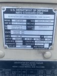
This is a MEP-804A that I don't know much history about. We recently purchased it as a running machine with the AC interrupter bypassed. It started and ran fine and the output frequency and voltage were correct and adjustable. It was connected for low voltage. I replaced the AC interrupter and wired everything back up like it should be. Everything seemed fine the new AC interrupter worked and the output voltage and Hz were correct at the terminal board. I ran it for a couple hours with no load just to make sure everything seemed to work. We started it and watched it run where we bought it, but never saw a load applied to it just did basic voltage and Hz testing on site.
Changes Made
After replacing the output interrupter and feeling confident that it was gonna run ok, I switched to high voltage. Nothing was changed other than the plate was moved to the HV output location. I fired it up checked the voltage and Hz all seemed well. I ran it for a little while and felt confident all was good. It was started and shut down multiple times at both the high and low voltage setting.
Current
I went to load test the unit a couple days later. I fired the generator up it starts and runs fine, but I get no output voltage. I noticed that when you hold the Master Switch in the Start position the volt meter and Hz meter come up and show the correct values. As soon as you let off the switch in the run position you lose the output voltage. You can rotate the switch back to the start position and the voltage comes back. The convenience outlet follows the same, it only shows voltage only when in the start position not the run position. I am getting the under voltage alarm, with the Master Switch in the start position you are able to clear it.
I don't have any service manuals or documentation on the machine. Can someone point me to where to find troubleshooting material. And even better yet does anyone have any suggestions on what it might be? I am very experienced in electrical troubleshooting, but this is my first generator of this type to work on.
Thank You
Kevin

Last edited:


