• Steel Soldiers now has a few new forums, read more about it at: New Munitions Forums!

  • Microsoft MSN, Live, Hotmail, Outlook email users may not be receiving emails. We are working to resolve this issue. Please add support@steelsoldiers.com to your trusted contacts.

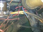
Anyone know where these 2 wires go?

1008Newbie

New member
20
0
1
Location
Greenfield, IN
Yes, I've been through the TM's and wiring diagrams. I still do not know where these 2 wires go, or if its normal for them to go nowhere. Pictures attached. 1 blue 1 pink/black, near driver side relay.

Thanks for any info you might be able to provide. Or flame me, anything would be welcomed at this point. aua
 

Attachments

beanman1

New member
324
1
0
Location
in the south
ok man the blue wire is the ground wire for the glow plug relay and the pink/black wire is ignition hot wire for the glow plug relay
 
Last edited:

1008Newbie

New member
20
0
1
Location
Greenfield, IN
Thanks

Thank you, that makes sense now.

They've rewired the glow plug relay to a toggle inside, so they must not have taken the time to insulate the wires at least, and since the glow plugs work I won't worry about it.

I might switch the whole system to 12V since I can't get the driver's side alternator to charge (even though the alternator is good) or the Gen 1 light to come on even though the bulb is good.

It seems much easier to bypass a bunch of wiring and make it 12V.
 

doghead

4 Star General /Moderator
Staff member
Super Moderator
Steel Soldiers Supporter
26,246
1,177
113
Location
NY
If you convert it to 12 volts, you will need gen 1 functioning correctly(it's the one you use as it is connected).

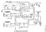
btw, in the back of the -20 TM, I can easily find those two wires Identified in the glow plug schematic.
 

1008Newbie

New member
20
0
1
Location
Greenfield, IN
You are right, I see it now on F-9. I miss having a printed manual. Digging through the pdf seems more difficult to me. I have printed out several wiring diagrams, but mainly for the charging system since thats what I started out troubleshooting.

Thanks for the reply.
 

doghead

4 Star General /Moderator
Staff member
Super Moderator
Steel Soldiers Supporter
26,246
1,177
113
Location
NY
What I have is, a folder on my computer(named cucv) with all the cucv TMs. With them saved on my computer, it is a breeze to look through them(not as nice as having a hard copy in your hand). When I view the files, I view them as thumbnails(so I can see the TM covers).
 

Warthog

Moderator
Super Moderator
Steel Soldiers Supporter
13,774
232
63
Location
OKC, OK
What I have is, a folder on my computer(named cucv) with all the cucv TMs. With them saved on my computer, it is a breeze to look through them(not as nice as having a hard copy in your hand). When I view the files, I view them as thumbnails(so I can see the TM covers).
Same here. I made a Manuals Folder and have sub-folders for all the different trucks. Under the CUVC folder I have sub-folders for wiring diagrams, alternator rebuilds, instrument cluster repair, etc....

On the wiring diagrams, I cut and pasted each one separately and when I am working on a specific item, ie starting system, I will color the wires I am working with and then print out that diagram. The first few pages of the Troubleshooting section tells you how to read the diagrams and what the wire colors are.

The tech manuals have a section that covers the testing methods for the Gens not working.

Why is it alot of people think it is easier to ripout the 24v system and then rewire the truck? I would much rather have a wiring diagram to figure out a problem, instead of reinventing the wheel each time I had a problem.

If you rewire it for 12v only are you going to draw yourself a new wiring diagram?

The 24v system is really simple once you study the diagrams and "see" how everything works together.


Right click on the thumbnail and choose "Open Link in New Window"
 

Attachments

Last edited:

1008Newbie

New member
20
0
1
Location
Greenfield, IN
Hi Everyone, my charging problem and Gen 1 light not coming on was resolved in a different thread. Thanks to help from Warthog and others, I located a corroded ground on my Gen 1 alternator, sanded it, applied dielectric grease and life is good.

Thanks to everyone.

By the way, I can't believe I was contemplating changing to 12V because of a corroded ground. It was much easier just to clean the ground than rewire the truck :oops:. I was thinking the problem was a bit more complicated, but it wasn't.
 
Top
AdBlock Detected

We get it, advertisements are annoying!

Sure, ad-blocking software does a great job at blocking ads, but it also blocks useful features of our website like our supporting vendors. Their ads help keep Steel Soldiers going. Please consider disabling your ad blockers for the site. Thanks!

I've Disabled AdBlock
No Thanks