• Steel Soldiers now has a few new forums, read more about it at: New Munitions Forums!

  • Microsoft MSN, Live, Hotmail, Outlook email users may not be receiving emails. We are working to resolve this issue. Please add support@steelsoldiers.com to your trusted contacts.

need Glow Plug Relay help

ranchhopper

Well-known member
1,631
139
63
Location
south elgin illinois
Yes understanding the system is helpful I have bought and sold quite a few of these and probably 60 percent of them had bad GPs first place I check is the resistor they go bad and put the full 24 volts to the GPs and fries them all. At least splitting the 12 volt load for the GPs and powering up the rest of the electrical system in the truck between both batteries will help get more life of the batteries in my opinion anyways. Since wiring the GP solenoid off the front battery after the resistor went bad I have never had any issues with killing one or the other batteries in my trucks.
 

Disciple

New member
247
4
0
Location
Eagan, Mn
At least splitting the 12 volt load for the GPs and powering up the rest of the electrical system in the truck between both batteries will help get more life of the batteries in my opinion anyways.
Well, you're getting closer, but still off a little I think. All of the 12V stuff in the truck runs off of the Front battery ONLY anyway. The ONLY thing the back battery is used for is creating 24V to turn the starter, and before bypassing the Resistor Bank, powering up the GP's by routing through the Resistor Bank to drop to 12V. Nothing 12V in the truck uses the back battery. Period!

The only real reasons I've been able to come up with for going with a 12/24V system like this is so these trucks could be used to Slave bigger trucks and tanks, etc. That, and by using a 24V starter, you cut the Amperage needed to turn it in half vs. a 12V starter, meaning easier starts (theoretically).
 

ranchhopper

Well-known member
1,631
139
63
Location
south elgin illinois
The power for the trucks 12 volt electric system comes from the battery closest to the firewall it comes off the negitive terminal through a red 8 gauge wire and goes to the power block with the two terminals on the upper driver side of the firewall
 

Disciple

New member
247
4
0
Location
Eagan, Mn
It doesn't matter if you hook your new feed wire to the + of the front battery or the - of the back battery, electrically it's the same thing and you are still only getting 12V+ from the FRONT battery.
Yeah. You just proved my point. Your 12V+ is only coming from the FRONT battery. Front Battery + is the same thing as Back Battery -. The power is coming from the FRONT battery for all the 12V in the truck.
 

mistaken1

New member
1,467
6
0
Location
Kansas City, KS
If your resistor on the firewall was bad it was shooting 24 volts to the GP solenoid by going to a 24 volt solenoid you dont burn out the solenoid but you still fry the 12 volt glow plugs.
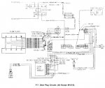
Doesn't a 12V feed go to the glow plug controller and from there that 12V goes through the pink/black 39B wire to one side of the glow plug relay coil?

Then the 12V runs through the relay coil and back to the glow plug controller on the light blue 505 wire?

When the glow plug controller grounds the light blue wire 505 then current driven by 12V runs through the glow plug relay coil creating an electromagnet and closing the relay's power contacts which in turn feeds the 24V output from the resistor on the firewall to the glow plugs that are in parallel?

As current flows from the batteries through the ideally balanced series-parallel circuit then this resistor/glow plug system acts as a voltage divider and drops 12V on the resistor and 12V on the glow plugs?

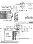
The way I read the schematic, 24V never goes through the glow plug relay coil.

I'll admit running 12V to a 24V coil will not burn it out but I question if 12V through a 24V coil will develop enough magnetic flux to close the relay contacts thereby sending voltage to the glow plugs.
 

Attachments

mistaken1

New member
1,467
6
0
Location
Kansas City, KS
The power for the trucks 12 volt electric system comes from the battery closest to the firewall it comes off the negitive terminal through a red 8 gauge wire and goes to the power block with the two terminals on the upper driver side of the firewall
The back battery negative post is the same electrical point as the front battery positive post. The other half of that 12V circuit is the negative post of the front battery which is bonded (connected) to the vehicle chassis.

When we ground the light blue wire with a manual switch to make the glow plug relay (solenoid) activate we are completing the circuit from the negative post of the front battery, through the chassis, through the blue wire, through the relay coil, through the pink/black wire, etc. until we ultimately reach the negative post of the back battery which is electrically the same point as the positive post of the front battery. (electrons move from negative to positive)

The back battery negative post 'floats' 12V above the vehicle chassis which is why the back battery cannot be used to power common negative ground 12V equipment mounted on the vehicle. Most of this equipment has it's chassis bonded to the negative input terminal. When you connect the back battery negative to this equipment that is mounted to the chassis there is a direct short between the back battery negative post (same electrical point as the front battery positive post) and the front battery negative post bonded to the chassis.
 

ranchhopper

Well-known member
1,631
139
63
Location
south elgin illinois
Doesn't a 12V feed go to the glow plug controller and from there that 12V goes through the pink/black 39B wire to one side of the glow plug relay coil?

Then the 12V runs through the relay coil and back to the glow plug controller on the light blue 505 wire?

When the glow plug controller grounds the light blue wire 505 then current driven by 12V runs through the glow plug relay coil creating an electromagnet and closing the relay's power contacts which in turn feeds the 24V output from the resistor on the firewall to the glow plugs that are in parallel?

As current flows from the batteries through the ideally balanced series-parallel circuit then this resistor/glow plug system acts as a voltage divider and drops 12V on the resistor and 12V on the glow plugs?

The way I read the schematic, 24V never goes through the glow plug relay coil.

I'll admit running 12V to a 24V coil will not burn it out but I question if 12V through a 24V coil will develop enough magnetic flux to close the relay contacts thereby sending voltage to the glow plugs.
Yes the wire from the + side bus bar goes to the resistor then over to the glowplug solenoid the problem is the resistor goes bad then fries the GPs I only route the 8 gauge wire from the front battery if the resistor is bad I dont change anything from stock configuration unless forced to because of certain components no longer being in serviceable condition. I also change the GPs to manual control useing either a push button or rocker switch when the GP controller cards go out if you know what you are doing I think manual control is much better.
 

ranchhopper

Well-known member
1,631
139
63
Location
south elgin illinois
No negitivity on my part sorry if I came across that way the last sentence in the above post just means to many guys go changing to manual GP control and really do some damage not knowing how to use the system.
 

mistaken1

New member
1,467
6
0
Location
Kansas City, KS
Yes the wire from the + side bus bar goes to the resistor then over to the glowplug solenoid the problem is the resistor goes bad then fries the GPs I only route the 8 gauge wire from the front battery if the resistor is bad I dont change anything from stock configuration unless forced to because of certain components no longer being in serviceable condition. I also change the GPs to manual control useing either a push button or rocker switch when the GP controller cards go out if you know what you are doing I think manual control is much better.
Yes the glow plug relay does get 24V but only to the power contacts not the coil contacts. In a correctly operating system that 24V is just for a moment until the current flow causes the voltage division between the resistor and the glow plugs.

If the resistor goes open no power to the glow plug relay. If it shorts then even with all the glow plugs working they will see all 24V and quickly stop working. (and be hard to get out)

Moving the wire from the load side of the resistor to the 12V terminal block does correct the issue of a bad resistor feeding 24V to the glow plugs by feeding only 12V to the glow plugs.

Installing a manual switch to operate the glow plug relay eliminates issues with a bad controller card and provides definite manual control over the glow plug heating cycle.

We are saying basically the same thing but I talk a lot longer! ;)

If one was to use 24V to feed the glow plug relay power contact and then installed 24V glow plugs and finally bypassed the controller card with a manual switch that would allow both batteries to carry the glow plug load and the starter load. This configuration would still need an isolated 12V coil relay unless one was to rewire the coil circuit for 24V as well.
 

doghead

4 Star General /Moderator
Staff member
Super Moderator
Steel Soldiers Supporter
26,246
1,176
113
Location
NY
You guys sure know how to keep a post simple!
 

cfish

New member
173
0
0
Location
Eastern/NC
Lol, so back to my original question. Is the way the previous owner set up my system going to damage anything or cause a small nuclear explosion under my hood?:mrgreen:
 

mistaken1

New member
1,467
6
0
Location
Kansas City, KS
Ok so I have been looking thru the TMs and pictures here of the GPR change out. Mine has the newer style GPR like the one in the CUCV facts picture. As i was looking under the hood yesterday, I noticed something strange. The two red leads with white markings coming from the sheilded area on the fire wall directly behind the airintake are cut. The one on the drivers side should have been going to my GPR, not sure where the other one went. Looks like someone made a jumper cable and attached the GPR directly to the 12v bus next to it. Isn't that sheilded area the the dissipator? Can someone explain what the previous owner did?

Post some pictures but it sounds just like what ranchhopper has been describing. Basically the glow plug circuit has been changed to 12V. The 24V feed through the resistor on the firewall has been eliminated in favor of a straight 12V feed by moving the wire that connected the glow plug relay to the passenger side of the resistor to the 12V bus next to the GP relay.

I calculate that the glow plugs will draw approximately 80A while heating so when I changed my M1009 over to 12V glow plug operation I ran a new #4 cable directly from the front battery positive (with a 175A fuse to keep the #4 wire from burning up my truck if it shorts to the chassis).

http://www.steelsoldiers.com/cucv/62408-story-my-cucv-12v-glow-plug-conversion.html

While the small wire that once connected to the resistor is being used as intended originally I feel that the wire that feeds the 12V diamond shaped bus is too small for the additional glow plug load. That being said many people have been doing just that for years without issue so I am going to say you will not have any problems with this particular modification.
 

Disciple

New member
247
4
0
Location
Eagan, Mn
Shouldn't go Nuclear on you anytime soon. If it does though, I think this country's in for a big hurtin' considering all the CUCV's we've got spread out around the country with this mod.

You should be just fine, I've been told that this mod is actually a change order from the Army because of the issue with the Resistor Bank changing impedance and frying your plugs.

One suggestion though, you said that the wire coming out of the driver's side of the Resistor Bank is just cut and hanging. You might as well remove the Resistor and the wire going into it from the Distribution Block on the passenger side and the wire that use to go to the GP Relay. You have the right relay, the one most guys here are using.

As long as everything is working the way it should, you should have years of trouble-free use with this setup.

Sorry, we got a little off topic for a while there but hey, if it weren't educational as well as fun we wouldn't be on SS!
 

doghead

4 Star General /Moderator
Staff member
Super Moderator
Steel Soldiers Supporter
26,246
1,176
113
Location
NY
Lol, so back to my original question. Is the way the previous owner set up my system going to damage anything or cause a small nuclear explosion under my hood?:mrgreen:
I think your fine. (I do the same modification to mine).
 

cfish

New member
173
0
0
Location
Eastern/NC
Shouldn't go Nuclear on you anytime soon. If it does though, I think this country's in for a big hurtin' considering all the CUCV's we've got spread out around the country with this mod.

You should be just fine, I've been told that this mod is actually a change order from the Army because of the issue with the Resistor Bank changing impedance and frying your plugs.

One suggestion though, you said that the wire coming out of the driver's side of the Resistor Bank is just cut and hanging. You might as well remove the Resistor and the wire going into it from the Distribution Block on the passenger side and the wire that use to go to the GP Relay. You have the right relay, the one most guys here are using.

As long as everything is working the way it should, you should have years of trouble-free use with this setup.

Sorry, we got a little off topic for a while there but hey, if it weren't educational as well as fun we wouldn't be on SS!

I'll just remove the resistor. Its alrready cut on bothe ends. There is no power getting to it. Thanks for the help. I am now certain I am almost as confused as before. Just kidding!
 

Doc Bingo

New member
29
0
0
Location
Peoria, Az.
HELP x 2

Ok ... so take off the 24v go get a 12v (part number st85) put it on then take it from there ... ??? Right ?

Alsowhere can I locate this gp relay under the dash or between firewall and the motor ?

Thanks and I appologize ahead of time just ready to figure this out so I can have a normal starting truck you know ...
 

cfish

New member
173
0
0
Location
Eastern/NC
Look at the top of the cucv forum. There is a section on CUCV facts, its on the first page and has good pictures to see what everyone is talking about. Its actuall located on the firewall next to the Brake master cylinder on the starboard side of it.
 

Doc Bingo

New member
29
0
0
Location
Peoria, Az.
I think thats the one I changed ... actually pretty sure ... I changed it to the 24v ... but I ll go to NAPA and get the 12v ... Anything else that I should look for while I am there or get from NAPA that needs to deff be replaced do to putting the wrong part in ?

Thanks,
 
Top
AdBlock Detected

We get it, advertisements are annoying!

Sure, ad-blocking software does a great job at blocking ads, but it also blocks useful features of our website like our supporting vendors. Their ads help keep Steel Soldiers going. Please consider disabling your ad blockers for the site. Thanks!

I've Disabled AdBlock
No Thanks