• Steel Soldiers now has a few new forums, read more about it at: New Munitions Forums!

  • Microsoft MSN, Live, Hotmail, Outlook email users may not be receiving emails. We are working to resolve this issue. Please add support@steelsoldiers.com to your trusted contacts.

Glow Plug Relay Rewiring help needed

Warthog

Moderator
Super Moderator
Steel Soldiers Supporter
13,774
232
63
Location
OKC, OK
You can install a new feed wire for the GP and run it directly from the front battery.

There are many people here that have used the 12v Terminal Block without any problem.

The way I decribe the setup is not my idea. Just restating what has already been discussed many times.

With clean connections and good plugs, the stock feed wire at the 12v block should be fine.

If you do run a new feed wire, make sure you have some type of load protection. The 12v Terminal Block has a fusible link built in.

UncleSam - I suggested installing the "new" manual switch wiring as a backup. And we don't yet know what else is wrong with the wiring. Many people will install this switch for the outside chance they run into an issue and need GPs where they are in the middle of nowhere. All that is required is a ground wire. Simple and easy.
 

doghead

4 Star General /Moderator
Staff member
Super Moderator
Steel Soldiers Supporter
26,246
1,179
113
Location
NY
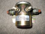
I did not notice anywhere in this thread, it mention the relay needs to have an isolated ground on the coil. The pictures of his relay, have me slightly concerned that, that may not be the correct relay. I suggest you test it before you use a GP controller card(or you could damage it).
 

Warthog

Moderator
Super Moderator
Steel Soldiers Supporter
13,774
232
63
Location
OKC, OK
Thanks DH. I took that for granted. The relay looks like it does have the isolation rubber feet.
 

ChiefMinion

New member
26
12
3
Location
Prescott, AZ
Doghead & Warthog,

Thanks for alleviating my concerns. Using the terminal block is simpler and will look nicer.

Doghead, if you point to illuminating information, I'll read it and try to absorb. Just because I don't understand doesn't mean I don't want to.

Both of you have a great weekend!
 

UncleSam

New member
58
3
0
Location
Anniston Alabama
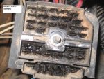
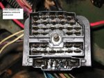
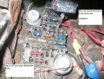
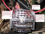
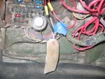
OK, I cleaned the terminal harness, all the contacts look good, I marked in the photos which terminal the cut wire goes to. I found where the other red wires go to, they go to the Harness wiring block just bove the GP relay, and they check 12V, and the spliced red wire that runs through the firewall inside to the top of the fuse box checks 24V, the OP may have rewired it for the starter since the only thing (I think) I have that 24V is my starter.

The photo of the fuse info added to photo.

Thanks

Uncle Sam
 

Attachments

UncleSam

New member
58
3
0
Location
Anniston Alabama
Thanks doghead, I've the correct relay, that I'm going to change before I replace the GP Module. BTW I ordered a new GP Module from CUCV Eletric, on the 28th of Aug, and have not received it yet, does it always take awhile to get it from them?

And thanks warthog, I'd plan on keeping the GP manual switch mounted but not hooked up as a stand by, and I'll rewire my as you have shown me.


I did not notice anywhere in this thread, it mention the relay needs to have an isolated ground on the coil. The pictures of his relay, have me slightly concerned that, that may not be the correct relay. I suggest you test it before you use a GP controller card(or you could damage it).
 

doghead

4 Star General /Moderator
Staff member
Super Moderator
Steel Soldiers Supporter
26,246
1,179
113
Location
NY
Sure looks correct.

To be sure it is, use an ohm meter and check for continuty between either of the 2 small studs, to the mount. There should be none.
 

mistaken1

New member
1,467
6
0
Location
Kansas City, KS
Warning Thread Drift Ahead

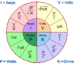
Ohms law: E=IR

So if we assume that the glow plugs parallel circuit is a 1 ohm series equivalent and then the firewall resistor is a 1 ohm resistance the we have 2 ohms total circuit resistance.

E/R = I
24/2 = 12 amps

If we eliminate the resistor and refeed the glow plugs parallel circuit 1 ohm series equivalent with 12V we get:

E/R = I
12/1 = 12 amps
 

Attachments

doghead

4 Star General /Moderator
Staff member
Super Moderator
Steel Soldiers Supporter
26,246
1,179
113
Location
NY
Ok, putting this in text, has me very confused. These are the numbers I came up with, but I am having a hard time believing them. I thought there was around 40 amps drawn by the stock GP system. Where did I go wrong here?

The 2 resistors on the fire wall are .280 ohm(each). Wired in parallel, that's .56 ohm.

The 8 GP are 1.5 ohm(each), wired is parallel that's 12 ohms.

The resistors are wired in series with the GPs. That's 12.56 ohms.


24 volts / 12.56 ohms=1.90 amps (Stock system)

12 volts / 12 ohms= 1 amp (12 volt supplied relay)
 

mistaken1

New member
1,467
6
0
Location
Kansas City, KS
I chose 1 ohm for math simplicity (which I need by the way).

Series and parallel resistances are calculated differently .

Series resistances can just add.
R total = R1 + R2 + R3 …
Parallel resistance uses the formula:
R parallel = 1 / (1/R1+1/R2+1/R3 … )
Identical resistors in parallel can be calculated using the value of one resistor divided by the total number in parallel.
R total = R value / N
So based on your measurements of the firewall resistor:
R total = 0.280 ohms / 2
R total = 0.140 ohms.
Then using the 1.5 ohm value for eight glow plugs we get:
R total = 1 / (1/1.5+1/1.5+1/1.5+1/1.5+1/1.5+1/1.5+1/1.5+1/1.5)
or R total = 1.5 / 8

R total = 0.1875 ohms
So now we add the two resistances together to get the total circuit resistance
R total = R1 + R2
R total = 0.140 + 0.1875

R total = 0.3275 ohms
Then using the formula I = E / R we get:
I = 24 / 0.3275

I = 73.28 amps
Then using the formula E = I x R we get:
E = 73.28 x 0.140

E = 10.26 volts (dropped across the firewall resistor)
Which means the other 13.74 volts is dropped across the glow plugs.


So if we assume one of our eight glow plug burns open we get:
R total = 1 / (1/1.5+1/1.5+1/1.5+1/1.5+1/1.5+1/1.5+1/1.5)
or R total = 1.5 / 7

R total = 0.2143 ohms
So now we add the two resistances together to get the total circuit resistance
R total = R1 + R2

R total = 0.140 + 0.2143

R total = 0.3543 ohms
Then using the formula I = E / R we get:
I = 24 / 0.3543

I = 67.74 amps
Then using the formula E = I x R we get:
E = 67.74 x 0.140

E = 9.48 volts (dropped across the firewall resistor)
Which means the other 14.52 volts is dropped across the glow plugs.


So if we assume two of our eight glow plug burns open we get:
R total = 1 / (1/1.5+1/1.5+1/1.5+1/1.5+1/1.5+1/1.5)
or R total = 1.5 / 6

R total = 0.25 ohms
So now we add the two resistances together to get the total circuit resistance
R total = R1 + R2

R total = 0.140 + 0.25
R total = 0.39 ohms
Then using the formula I = E / R we get:
I = 24 / 0.39

I = 61.54 amps
Then using the formula E = I x R we get:
E = 61.54 x 0.140

E = 8.62 volts (dropped across the firewall resistor)
Which means the other 15.38 volts is dropped across the glow plugs.

So when one glow plug burns out the rest see a higher voltage until another burns out which means the rest see a higher voltage until they are all burned out.


12V conversion:

So if we go back to the that initial 0.1875 ohms for the glow plugs alone without the resistor in series and use 12 volts nominal we get the following:
I = E / R:
I = 12 / 0.1875

I = 64 amps (in the 24V circuit we had 73.28 amps)
 
Last edited:

1stSarge

Member
428
5
18
Location
Mount Vernon, Ohio
Mistaken has it perfect!

I remember complimenting him on breaking this down in another thread. But here he has out done himself.

This is exactly correct, I am working up a graphic to illustrate, but I do have one question Dog, you said the resistance was .28 ohms, (each) is that the resistance on each resistor in the bank, or is it the total resistance of the bank? Remember there are two resistors in there. See Table 2-4 Step 5 of the -20, the total resistance of the bank should be .28.
 

doghead

4 Star General /Moderator
Staff member
Super Moderator
Steel Soldiers Supporter
26,246
1,179
113
Location
NY
The part number in the -20P is 14076847 (for 1 resistor on the firewall).

4 PAOZZ 11862 14076847 RESISTOR,FIXED,WIRE qty2


Here's a link to a parts quote with the specifications.
http://www.ctg123.com/rapid-quote-system/request/?p=14076847


What I was attempting to do originally was, calculate the amp load with stock 24V or converted to 12V.

Thank you very much, Mistaken1.
 
Last edited:

doghead

4 Star General /Moderator
Staff member
Super Moderator
Steel Soldiers Supporter
26,246
1,179
113
Location
NY
So, in reference to post# 19. It is safe to say, the difference when resupplying to 12 volts is, you double the amp load on the front battery and eliminate all load on the rear battery (even though the amp load of the system is reduced slightly).
 

doghead

4 Star General /Moderator
Staff member
Super Moderator
Steel Soldiers Supporter
26,246
1,179
113
Location
NY
Also, my next concern is the wire size and fusible link capacity on the 12v wire that supplies the truck(when adding the GP load to it).

I personally have had no issues with a new short jumper wire(drawing off the 12v circuit).
 

1stSarge

Member
428
5
18
Location
Mount Vernon, Ohio
The way I am understanding #19 is that it is incorrect, but I might be reading it wrong. Voltage and amperage are inversely proportional. Double one will half the other. Most people know that they are inverse, but don’t forget, they are proportional. Wattage will remain the same. ( ExI ).

The amperage is reduced slightly because you are not burning off any power as heat in the resistors.

So to clarify part of Mistaken’s post, notice that when a plug fails open while the voltage goes up, the total amp draw decreases.

----Normal
13.74 volts across plugs---
73.83 amps---

-----One plug failed open
14.52 volts across plugs---
61.54 amps---


So on the 12 volt wiring size, when you say “supplies the truck” I will go from there assuming you are saying the wire that goes to the glow plug relay. With that in mind;

I am not a harness engineer (yes there is such a thing ) nor did I stay at a Holiday inn express last night, however in my humble opinion, 8 gauge would be the correct choice for a short run to the relay from the 12 terminal block, and I would use 6 gauge for a longer run, say from the front battery.

The fusible link should be a blue 12 gauge.
 

doghead

4 Star General /Moderator
Staff member
Super Moderator
Steel Soldiers Supporter
26,246
1,179
113
Location
NY
I have used 8 ga wire for my jumper (and recommend that to others).

My question is, is the red wire that goes to the 12v junction stud(and its fusible link) adequate for the additional load when tapped for 12v supply to the GP relay.

I have always been sure to NOT have my lights or any other 12v load on while my GPs cycle(since the 12v resupply.
 

mistaken1

New member
1,467
6
0
Location
Kansas City, KS
#8 wire will take approximately 472 amps before the copper melts.

The insulation on the other hand can not take that much amperage before heat in the copper wire begins to degrade/melt/burn the insulation. How much amperage is a function of the insulation type and the ability of the wire to dissipate heat (e.g. free air verses tightly bundled in a wiring harness)

For short term use the wire feeding the 12V bus will work but would not hold up to hours of glow plug draw (neither would most of the glow plugs). This is evidenced by the fact that you have been drawing power from the 12V bus without ever opening the fuse link protecting the wire feeding the bus.

When I measured my glow plugs with an ohm meter most were 1 to 1.2 ohms. If we rerun that glow plug parallel calculation using 1 ohm per glow plug the result is 0.125 ohms (1/8=0.125). The using 12V I get 96 amps (I = 12 / 0.125).

Also we are not counting loss in the wire and connections as well as the idea that the voltage drops when under a load (I have never measure the exact drop when the glow plug are energized) but still the glow plugs are a load, but it is a short term load.
 
Last edited:

UncleSam

New member
58
3
0
Location
Anniston Alabama
doghead, On teh GP relayy, there is no continuty between either of the 2 small studs, to the mount, but there is continuty between the 2 small studs, is this the way it should be?

Also I'm wanting to add a mechanical water temp gauge. The question I have is does the GP Module use the front sending unit mounted on the left front head have anything to do with the operation of the GP Module?

I was thinking that it uses the temp sensor mounted at the left rear on the engine on intake, but I wasn't sure..:confused:


Sure looks correct.

To be sure it is, use an ohm meter and check for continuty between either of the 2 small studs, to the mount. There should be none.
 

Warthog

Moderator
Super Moderator
Steel Soldiers Supporter
13,774
232
63
Location
OKC, OK
doghead, On teh GP relayy, there is no continuty between either of the 2 small studs, to the mount, but there is continuty between the 2 small studs, is this the way it should be?

Also I'm wanting to add a mechanical water temp gauge. The question I have is does the GP Module use the front sending unit mounted on the left front head have anything to do with the operation of the GP Module?

I was thinking that it uses the temp sensor mounted at the left rear on the engine on intake, but I wasn't sure..:confused:
The two small terminals should have continuity between them. This is what energizes the relay inside the unit. Power on one terminal, ground on the other.


Some relays use the mount as the ground. If you install one of these the GPs will be energized all thee time, as the hot wire is hot all the time.

I will check to see which sender the GP system uses. I don't recall right off hand.
 
Top
AdBlock Detected

We get it, advertisements are annoying!

Sure, ad-blocking software does a great job at blocking ads, but it also blocks useful features of our website like our supporting vendors. Their ads help keep Steel Soldiers going. Please consider disabling your ad blockers for the site. Thanks!

I've Disabled AdBlock
No Thanks