M99821T
New member
- 14
- 1
- 3
- Location
- Richland/WA
First post! Got the itch to pick up a HMMWV last summer (first military vehicle), and I found 86 M998 2-man for a really good price on Gov Planet. The inspection on Gov planet listed quite a few "issues" (no working exterior lights, dripping leak from transfer case...), but it had the front winch, 100 amp 28/14V alternator, 6.5L, and was refurbed in Maine in 2007. 5,300 mile on the odometer. Do they reset the odometer after refurb? Long story short, received it in late October and was pleasantly surprised that all the lights worked and the leaking transfer case was actually a drip in the undercoating.
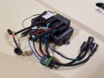
I decided to make use of the dual voltage alternator so I could add some security features. I picked up a Bussmann 15303-2-2-4 waterproof relay/fuse box and roughly followed the thread below.
https://www.tacomaworld.com/threads/diy-build-and-install-a-bussmann-rtmr-fuse-relay-block.399454/
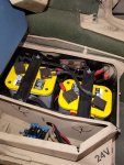
Pictures of the battery box with relay/fuse box connected. One of the batteries was dead when I received the HMMWV, so swapped the mil batteries for Optimas. Relay/fuse box and 14V from the alternator are connected to the rear battery (first battery in series; the one connected to ground).
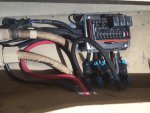
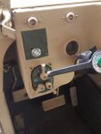
Connections on the side are for 5 fuse circuits and connections coming out the bottom are for the 5 relay circuits. I connected 3 relays to the accessory function on the push button start.
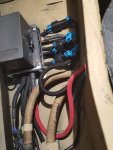
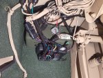
Wiring...cables and wires into and out of the battery box went through an existing hole next to the shunt, along the frame rail tied to the starter/24V supply cables, and up to the engine compartment through a channel in the body behind the dog house.
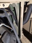
I ran the cables and wires along the base of the windshield to a fuse holder and then to the alternator.
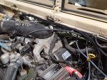
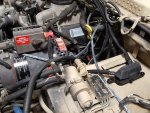
I know others have done similar things, but I just wanted to share my version.
Jared
I decided to make use of the dual voltage alternator so I could add some security features. I picked up a Bussmann 15303-2-2-4 waterproof relay/fuse box and roughly followed the thread below.
https://www.tacomaworld.com/threads/diy-build-and-install-a-bussmann-rtmr-fuse-relay-block.399454/
Pictures of the battery box with relay/fuse box connected. One of the batteries was dead when I received the HMMWV, so swapped the mil batteries for Optimas. Relay/fuse box and 14V from the alternator are connected to the rear battery (first battery in series; the one connected to ground).


Connections on the side are for 5 fuse circuits and connections coming out the bottom are for the 5 relay circuits. I connected 3 relays to the accessory function on the push button start.

Wiring...cables and wires into and out of the battery box went through an existing hole next to the shunt, along the frame rail tied to the starter/24V supply cables, and up to the engine compartment through a channel in the body behind the dog house.

I ran the cables and wires along the base of the windshield to a fuse holder and then to the alternator.


I know others have done similar things, but I just wanted to share my version.
Jared


