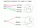
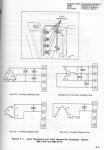
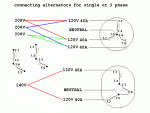
Ok I see the point. They do not make single phase 120V and 240V at the same time. In that case, the above reconnection diagram could apply. The AC gensets I mentioned all show to be three-coil, six-wire sets. Trying to study the manuals from a standpoint of changing a wire or two and having 120+240V single phase, the MEP-016 manual figure 6-3, figure 8-1B, and best of all figure 8-3 seem to show a large terminal strip with 6 junctions. These are possibly the '6 wires' which should disappear into the alternator itself. Figure 10-1 is a pretty good diagram, showing the voltage selector switch contacts labeled "S1" and tagged with various terminal numbers. Unlike a conventional electronics diagram, the switch is represented in the electrician's manner so it is not clear at first what connections are made in any specific mode. diagram FO-1 also shows the switch S1 and what wires go to it, but not the important part which is the insides of the switch. That's the missing information. From fig. 10-1 would be the place to start any divinations.
For the 5K set, MEP-017, table 7-1 shows the connections for its switch S1. This in conjunction with diagram FO-1 might clear things up as to the switching and any rewiring to be attempted. Diagram FO-2 is probably the most useful for divining.
In either case, it is entirely conceivable that adding another switch or perhaps simply a wire could allow the set to be placed in the 240V position and derive two 120V supplies to emulate house current. I'll draw some pictures on the diagrams, might be too big to post here due to 640x480 restriction.


