• Steel Soldiers now has a few new forums, read more about it at: New Munitions Forums!

  • Microsoft MSN, Live, Hotmail, Outlook email users may not be receiving emails. We are working to resolve this issue. Please add support@steelsoldiers.com to your trusted contacts.

#2 MEP 805B oh the joys

Guyfang

Moderator
Staff member
Moderator
16,713
23,965
113
Location
Burgkunstadt, Germany
Look at the schematic, and then find wire T-1, (L-1) T-2, (L-2) and T-3, (L-3). They come directly from the G-1, (main generator) to the TB-1. From there they go directly to CB-1. Wire T-0 goes from the G-1 to TB-1, connection, (Post) number 10. Measure from connection 10 to the three phases. Then you know what the G-1 is putting out.

What are the post numbers of the bottom 6 posts?

ALWAYS, repeat, ALWAYS, hold up the starter switch for a few seconds longer, after you THINK the set has started. A few seconds won't hurt. The starter is locked out by the magnetic pickup. If he starter grinds, you need to look at the mag pickup.
 

155mm

Chief and Indian
Steel Soldiers Supporter
1,177
388
83
Location
Guymon, OK
I got distracted with the control box cleaning and remount all the controls on the backplane, now the dc power light only lights after i start to crank then flickers while cranking, engine doesnt start now. ugh!!! I see why everything was loose on this backplane, i think technicians were hunting for a problem by changing parts. It got cold and dark so I said foowee on it for tonight.

I think the bottom row of post #'s on the tb1 are 1,2,3.... I didnt look while I was out there.

Also found the power potential transformer wasnt mounted and the wires had tape tags on them. I think I ended up with a controlled exchange model.

If its cold tomorrow, i will pull the whole control box and undo everything i did today, but in the shop with a H82 blowing on me. Until this jenny #2 proves itself worthy enough, its staying outside on the ground..... plus I havent found a trailer yet to put it on. Still have a WTB for a m200a1 in the classifieds.
 
Last edited:

155mm

Chief and Indian
Steel Soldiers Supporter
1,177
388
83
Location
Guymon, OK
#2 has returned to the land of the living, and with the modified starting sequence that baxter suggested, it now makes power, but hertz is off. If i hold the start sw, it always gives me an overvoltage fault, but if i let it start and come up to speed then hit the starter again it doesnt give me the fault.

guyfang, I checked all of my parts with the TM, they are correct.

I didnt FIX anything, but I did remove all the boxes and the backplane, clean them up, used can-o-air to blow out the connectors and put it all back together and now it works. The only thing that I did differently than yesterday, was I ran the slave to a 4 deuce jenny when I was starting #2 multiple times rather than to my 5T.

IMG_0947[1].jpg IMG_0950[1].jpg
 

Guyfang

Moderator
Staff member
Moderator
16,713
23,965
113
Location
Burgkunstadt, Germany
Sometimes that's the only thing equipment needs. TLC.

When you get the overvoltage Fault, can you hit the fault indicator reset and clear it?
 

baxter462

Member
79
2
8
Location
Salt Lake City Utah
That's great, almost done!

What hz is it producing? Does the hz displayed match the actual hz as measured with a meter? The frequency is obviously a function of engine rpm. There is of course the 50/60 hz switch on the panel inside the box, and the engine rpm can be adjusted with a potentiometer on the governor control board. Maybe Guyfang can provide is with the actual adjustment procedure?
 

155mm

Chief and Indian
Steel Soldiers Supporter
1,177
388
83
Location
Guymon, OK
Fault reset clears the over voltage, then you just adj volts down and stays gone.

The switch in the box is on 60/400 hz, i dont have a meter fancy enough to measure hertz but i do have an electrician friend that does have one. I thought the motor sounded like it was running slow, the throttle is against the stops at wide open actual hz that i am getting is 52, will not adjust up with the sw, but it will go down
 
Last edited:

Guyfang

Moderator
Staff member
Moderator
16,713
23,965
113
Location
Burgkunstadt, Germany
Do you think the engine is running at the right speed? What does the hertz meter read.

I cant remember just how its adjusted, but if it isn't reading anything, an adjustment aint gonna help. I had the procedure about 7 years ago, when I last laid hands on such a beast. Can't remember what it was. Sure wish I had not tossed that stuff all out.

When you screwed the gov back onto the Backplane, did you look to see if the electrical connector was in good shape. That plug often got bent out of shape, by rough installation.
 

155mm

Chief and Indian
Steel Soldiers Supporter
1,177
388
83
Location
Guymon, OK
I think the engine is running slow, hz reads 52.

All if the plugs and sockets looked good, had to get a magnifer out to see in the sockets.
 

baxter462

Member
79
2
8
Location
Salt Lake City Utah
I'd just quickly validate with your friend's dmm that the actual frequency matches the display, then I'd try bumping up the rpm with the potentiometer on the governor module. I think it is labeled "speed" or something self explanatory like that. Just note the starting position so you can move it back if needed. Since someone was obviously messing with that generator and swapping parts and such, it is possible they messed up all the potentiometer settings too
 

baxter462

Member
79
2
8
Location
Salt Lake City Utah
I just went and looked at both of mine. The potentiometer is called "speed trim." Mine are at about 70% and 80% on my two generators. Just for kicks, I adjusted one all the way down to zero, and the frequency was 53hz. So, if yours is all the way down (counter clockwise), there's hope of getting the frequency up to 60. Otherwise, there probably isn't enough adjustment. I'd also check the frequency switch on the governor module. Make sure both dip switches are off.
 

Guyfang

Moderator
Staff member
Moderator
16,713
23,965
113
Location
Burgkunstadt, Germany
Give it a try!

And there is no fault displayed on the CIM?

Does the A-6, Electric Actuator look like its been changed? If you get no reaction to adjusting the Pot Speed Trim, go to Work Package 0162, for test info on the electric actuator.

Interesting enough, the TOC, (Table of Contents) lists the Work Package for the electric actuator as 0172. I must have gone through the GD manual 22 times before I found it. The old manual had it right. This new manual is not what I call user friendly.
 

155mm

Chief and Indian
Steel Soldiers Supporter
1,177
388
83
Location
Guymon, OK
Speed trim was about 70, adjusted it up, and no dice, still had 52 hz. Stepped over to the IP, it was WOT against the adj. skrew, so I let the skrew out a bit, and the HZ came up. Adjusted the speed trim down and the motor went to surging just a bit, so I adjusted it back to 70 and made all my HZ adjustments at the IP. Now have a perfect 60 HZ. Now when I start up the motor, it flashes the field for me without having to do the 2nd step of hitting the starter again. Still have a CMOS voltage (light 5) on the board, but everything seems to be working properly. Will know more soon as i get this little trailer dissassembled so I can move #2 around.
 

baxter462

Member
79
2
8
Location
Salt Lake City Utah
That's great. I'm wondering if you'll run into an issue though having the rpm limited by the stop screw on the injection pump. Once you put a load on it, it won't be able to increase fuel delivery to compensate, and the hz will drop. I think the screw needs to be backed out so the electric actuator can increase fuel delivery under load. One of my generators had a surging rpm issue, and I took care of it by adjusting the "gain" potentiometer which is right next to the speed trim pot you already played with.

I'm sure there is an actual procedure somewhere to get everything set properly though.
 

155mm

Chief and Indian
Steel Soldiers Supporter
1,177
388
83
Location
Guymon, OK
Guyfang, actuator looks the same as the IP, doesnt appear to be changed.

No faults on CIM, army book shows it as 5-43.

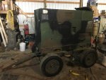
I have been a bit distracted today, been working on getting a 'trailer' to put #2 on so i can move it to get load tested. I started off with a 2 axle 400hz load tester and skinned off the load tester. Had to put wheel bearings and seals in before I put a real load on this trailer.

View attachment 664970

View attachment 664971

I will spend this evening digging through the book to see if there is an actual way to set up the speed controller..
 
Last edited:

Guyfang

Moderator
Staff member
Moderator
16,713
23,965
113
Location
Burgkunstadt, Germany
Yes there is a procedure. I used to have it, got it from a CECOM LAR. But sadly tossed it away. I am closing my eyes, and thinking back. I have yet to find it in the TM, so assume its not there.

Turn the speed trim until you have 65 hertz. Adjust gain until unstable. Re adjust until stable. Apply load. If the load is unstable, adjust gain pot. If the hertz drops below 60 hertz, adjust speed trim. Drop load. If the load is unstable. start again. Please do not hold me to this. It's been long and far away since I did this. I will go look on my second laptop. It might be there, but I don't think so.
 

155mm

Chief and Indian
Steel Soldiers Supporter
1,177
388
83
Location
Guymon, OK
Got #2 skidded on a trailer today. Tried guyfang's procedure but could only get her to get unstable by turning trim down, it would never go past 60 hz but it would go down. I am thinking i am limited on going up any more by the set skrews on the ip. I will set up the load tester tomorrow and loosen the set skrews on the ip so i can get more hz, then try turning the trim down and see if i can get any reaction

IMG_0966.jpg
 

155mm

Chief and Indian
Steel Soldiers Supporter
1,177
388
83
Location
Guymon, OK
Had a bit of delay of game today, had to call some coyotes.

Turned every skrew all the way up, nothing happened. So I go to the IP and loosed the stop skrew, had like 65.5HZ, and then skrewed down the trim and the HZ came down and the actuator light on the box came on. All of my rhostats actually started working now that the IP is opened up so that they could actually do their jobs. The up and down HZ switch actually works too.

This ol girl is getting closer to being back to normal, just takes alot of WTF moments. Will get the load tester hooked up tomorrow, and do a proper test, see what we can come up with next to fix. The 'low cmos voltage' light has me wondering, but as long as everything works, I dont care.
 

155mm

Chief and Indian
Steel Soldiers Supporter
1,177
388
83
Location
Guymon, OK
Well, its only been on the load tester at 33Kw load for over an hour, and all is well. I guess all my cussing and discussing paid off, it runs just as it is designed. Water temp never exceeded 170*F, HZ maintained 60.0 except under max shock load of 33kw, then it only drooped to 59.7HZ for a spit second, I didnt think that was out of tolerance. I get a little puff of black smoke when I shock load it, but exhaust runs clean after I got the cobwebs cooked out, that took maybe 5 minutes under a full load.

For those of you who are paying attention to details, the amps arent the same, I have couple load coils in the load tester that have broken and havent found a place to source them to get them replaced.

IMG_0976[1].jpgIMG_0973[1].jpg
 
Last edited:
Top
AdBlock Detected

We get it, advertisements are annoying!

Sure, ad-blocking software does a great job at blocking ads, but it also blocks useful features of our website like our supporting vendors. Their ads help keep Steel Soldiers going. Please consider disabling your ad blockers for the site. Thanks!

I've Disabled AdBlock
No Thanks