• Steel Soldiers now has a few new forums, read more about it at: New Munitions Forums!

  • Microsoft MSN, Live, Hotmail, Outlook email users may not be receiving emails. We are working to resolve this issue. Please add support@steelsoldiers.com to your trusted contacts.

2008 A1R with 260a charging questions

GeneralDisorder

Well-known member
Steel Soldiers Supporter
2,080
5,311
113
Location
Portland, OR
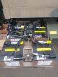
Replaced all the battery cables today along with new terminal covers (several terminals were crushed and one had a crack (PVT Snuffy had wrecked them) and installed a brand new voltage regulator from 2018 to rule out the last few questions. So far I've not experienced any behavioral issues on my daily drive home.

LMTV Battery Drawer.jpg

We shall see what the future holds.
 

Ronmar

Well-known member
3,886
7,550
113
Location
Port angeles wa
Did you replace your LBCD at some point? been involved in so many problems, I am forgetting who had what problem:)

As it takes a little while for the alternator field to collapse when the alt has a major load change, The LBCD has a large capacitor bank in it to absorb the alternator energy when the LBCD commands a battery relay disconnect due to overload. If that cap bank wasn’t functioning properly, an intermittent battery connection could cause voltage spikes…
 

GeneralDisorder

Well-known member
Steel Soldiers Supporter
2,080
5,311
113
Location
Portland, OR
LBCD was replaced - had blown capacitors and a loose stud in addition to very nasty connections. That was replaced a while ago and I have since upgraded the battery disconnect relay to the current Cooper-Bussman fully enclosed unit and it works correctly using the toggle switch in the cab as well as the one in the engine bay. During the over-voltage conditions the battery disconnect has never activated so I do not believe this to be related. My original battery disconnect relay was not functioning and I believe that is a result of a bad solder joint on one of the ring terminals from the potted control box hanging off the side of the unit. The ring terminal was loose in the potting.......

I scoped the F+ regulator output and when the OVCO occurs you can easily see in the scope trace where the F+ goes from it's normal PWM of around 20-24v to pegged at 28v+ when the voltage starts climbing. The Niehoff engineer was absolutely correct that the F+ is being fed intermittent 28v B+. The question is how and where?

I was able to "find" the repair manual for the N1224-1 and in there it has the diagram for the front end bell wiring - this is accessible by removing the drive pulley and the front sheet aluminum covers. The repair manual gives this diagram:

N1224-1 Field Coil Leads.jpg

I figured that the short to B+ must be occurring inside the end-bell where the F+ enters from the back and (apparently - according to the diagrams) exits from the front and connects to this Red F+ lead. So I figured - why not just bypass this whole potted section and wire the F+ directly from this lead to the voltage regulator. So I did:

N1224-1 Stator Conections.jpg

N1224-1 F+ Re-route.jpg

I hooked this up to the F+ output from the voltage regulator and....... it didn't work :(

All I got was flashing amber lights on the VR. I had to get home so I undid the connections and put it back to normal although in retrospect I should have done a scope trace on it. According to the diagram I previously posted the F+ is fed directly from the VR pin A with nothing in-between......

I know more than I did when I started but still no resolution at this time. I'm going to add some Deutsch connectors to this mess so I can select where I drive the F+ from and also run more scope traces.
 

GeneralDisorder

Well-known member
Steel Soldiers Supporter
2,080
5,311
113
Location
Portland, OR
Ok. Have been diligently chipping away at this issue and I believe it is now resolved.

1. Swapped the alt. Found an ugly duckling on the cheap due to an upper mounting bolt thread issue (stripped), bent fan and fan cage, missing pulley and ground strap threads stripped..... Fixed all that with fan, cage, and pulley from my existing alternator and some heli-coil thread repairs. Alt is a reman from 2016 and I have a 2018 voltage regulator - worked the same as the original alt. That is to say most of the time it worked fine but withing 1-2 drives it would go into over-voltage cut out. This test essentially rules out the alternator and the VR as culprits for this issue.

2. Decided to go back to the LBCD and just bypass it completely. I had previously disconnected the E terminal wire to it from the VR, and only recently had I installed a new battery disconnect relay since mine was bad (bad solder joint on the ring terminal inside the potted control box) and figured it couldn't have been disconnecting the batteries due to that failure. The battery disconnect relay has been replaced and upgraded to the new Bussman fully enclosed unit and is working with the cab and engine bay switches.

So after putting the load side wires on the battery side studs and unplugging the cannon plug on the LBCD..... the over-voltage cut-out (OVCO) problem was entirely resolved. I drove the truck 200 miles this way and never had a single issue. Took it off-road and everything. Multiple starts and stops, etc. No issues whatsoever.

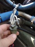
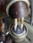
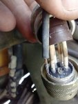
3. So from this evidence I decided to wring out the wiring on the LBCD cannon plug just for educational purposes. I understand that with the 260A alternator and the fact that it is highly unlikely as an educated LMTV owner that I would ever connect the batteries incorrectly that it is essentially superfluous, but I have a burning desire to know and understand WHY in detail so I began this process anyway. If nothing else it's a good exercise in testing.... I started with pin A on the LBCD and immediately ran into a problem....... pin A is supposed to be the "ground reference" for the LBCD. It read open (infinity) on my meter. This wire runs all the way to the battery disconnect box and connects to the bolt where the main battery ground cable connects. I poked the wire in several places and got nothing. I worked my way to the LBCD plug and just an inch from the plug I still had nothing. I opened up the back of the plug and tugged on the ground wire and it came right out of the connector!

IMG_20220530_173529347.jpg

IMG_20220530_174308471.jpg

IMG_20220530_174315713.jpg

This is clearly a case of a cold solder joint or the wire being tinned and never soldered from the factory. This flaw has clearly existed with this truck from manufacture.

There was enough oxidation that I was not able to solder it without replacing a section of wire:

IMG_20220530_184747062.jpg

I now have a solid ground for the LBCD. I swapped the load side cables back to the load studs and test ran it. LBCD indicator light went green and all seems to be right. I have not been able to cause an OVCO condition since this repair with the usual methods that incite this behavior.

I still do not understand why this would cause the OVCO. I had previously disconnected the E terminal from the VR (the only connection between the alternator and the LBCD) and it still occurred.
 
Last edited:

GeneralDisorder

Well-known member
Steel Soldiers Supporter
2,080
5,311
113
Location
Portland, OR
Had a scare this afternoon. Driving home from the liquor store and noticed the 28v gauge reading 30v.... awe @#$%$#!

Then I noticed the 14v gauge was reading 13.5v and the 28v gauge wasn't rising.... it was steady at 30v. Strange......

I pulled into my driveway and left the truck running while I grabbed my meter. 28.0v, and 14.0v on the battery..... WTH?

PDP panel reads 27.3v and 13.4v.... exactly as it should.

Shut the truck down and the 28v gauge does not drop to 0v. It hangs about 2v above the bottom. I cycled the power on and the MMDC did it's usual zeroing of the gauges and I waited till all the clicking and clacking was done to hit the starter. Right back to 28v on the gauge.

So just a word of caution - the A1/A1R trucks with the MMDC controlled gauges - more than once I've seen the gauges not entirely calibrate before they begin readout of data. They are not that accurate and no substitute for a DMM. Honestly I think I'm going to add some digital voltage gauges to the panel that feed directly from the PDP supplies (fused of course) or I'll replace the MMDC CANBUS gauges entirely with digital or analog units that I can trust all the time - not just when the MMDC decides to properly calibrate after startup.

Previous fix with the LBCD connector is still valid. No OVCO symptoms. Flashing greens on the VR and solid green on the LBCD.

I do wonder if the short time this LBCD was exposed to this environment if it may have cause damage to the capacitors with that floating ground issue.

What a nightmare. 8 months it took to figure this out.
 

GeneralDisorder

Well-known member
Steel Soldiers Supporter
2,080
5,311
113
Location
Portland, OR
Yea, not a big fan of the MMDC. Too many eggs in one basket...
I bought several surplus units real cheap from eBay and I have to say - other than the staggering lack of foresight exemplified in locating the pressure transducers on the circuit board instead of moving them off the board into their own environment - all the units I have plugged in have worked without issue. They display accurate enough information for a soldier - the gauge was still (barely) in the green so (y)

If they fail you do lose all your gauges. Truck still runs and doesn't care though which is a plus.
 

GeneralDisorder

Well-known member
Steel Soldiers Supporter
2,080
5,311
113
Location
Portland, OR
I daily drive my truck and it's now been a solid week of driving every single day and the issue has not returned. So I hope that my anguish of 8 months of troubleshooting helps someone out someday. The takeaway here is that the Alternator, Voltage Regulator, LBCD, Batteries, and EVERY connection between them is all part of the charging "ecosystem" of these trucks and regardless of what the manual says - when you encounter an issue check every component and it's wiring with ABSOLUTE THOROUGHNESS to ensure you haven't missed a possible issue. Any truck that's new to you - don't just check - remove and clean and dielectric every connection.

After this I do have more faith in the 260a brushless Niehoff though. Overall it seems quite the tank of an alternator (both of mine are good obviously). I'm still planning to try to implement the CANBUS data from it to a display.
 

GeneralDisorder

Well-known member
Steel Soldiers Supporter
2,080
5,311
113
Location
Portland, OR
Thats quite the effort and some badass troubleshooting. Good job.
Thanks! It took many months but I got there in the end. I have my suspicions that this fault may have been responsible for the truck never being maintained and eventually being discarded with under 2k miles on it. Everything on the truck seemed to be original from 2008. Best guess is the truck was perpetually deadlined due to this fault. I can't think of any other way the Army could own it for 8 years (at least) and never do any annual or bi-annual service to it.
 

MatthewWBailey

Thanks for this site. My truck runs great now!
Steel Soldiers Supporter
863
1,567
93
Location
Mesa Colorado
... I had previously disconnected the E terminal from the VR (the only connection between the alternator and the LBCD) and it still occurred.
I'm looking thru this trying to get on the same page. When you say E term from VR is the only connection to LBCD, where is that shown? The posted schematics only show this...
 

Attachments

Last edited:

MatthewWBailey

Thanks for this site. My truck runs great now!
Steel Soldiers Supporter
863
1,567
93
Location
Mesa Colorado
Thanks! It took many months but I got there in the end. I have my suspicions that this fault may have been responsible for the truck never being maintained and eventually being discarded with under 2k miles on it. Everything on the truck seemed to be original from 2008. Best guess is the truck was perpetually deadlined due to this fault. I can't think of any other way the Army could own it for 8 years (at least) and never do any annual or bi-annual service to it.
Ok. Have been diligently chipping away at this issue and I believe it is now resolved.

1. Swapped the alt. Found an ugly duckling on the cheap due to an upper mounting bolt thread issue (stripped), bent fan and fan cage, missing pulley and ground strap threads stripped..... Fixed all that with fan, cage, and pulley from my existing alternator and some heli-coil thread repairs. Alt is a reman from 2016 and I have a 2018 voltage regulator - worked the same as the original alt. That is to say most of the time it worked fine but withing 1-2 drives it would go into over-voltage cut out. This test essentially rules out the alternator and the VR as culprits for this issue.

2. Decided to go back to the LBCD and just bypass it completely. I had previously disconnected the E terminal wire to it from the VR, and only recently had I installed a new battery disconnect relay since mine was bad (bad solder joint on the ring terminal inside the potted control box) and figured it couldn't have been disconnecting the batteries due to that failure. The battery disconnect relay has been replaced and upgraded to the new Bussman fully enclosed unit and is working with the cab and engine bay switches.

So after putting the load side wires on the battery side studs and unplugging the cannon plug on the LBCD..... the over-voltage cut-out (OVCO) problem was entirely resolved. I drove the truck 200 miles this way and never had a single issue. Took it off-road and everything. Multiple starts and stops, etc. No issues whatsoever.

3. So from this evidence I decided to wring out the wiring on the LBCD cannon plug just for educational purposes. I understand that with the 260A alternator and the fact that it is highly unlikely as an educated LMTV owner that I would ever connect the batteries incorrectly that it is essentially superfluous, but I have a burning desire to know and understand WHY in detail so I began this process anyway. If nothing else it's a good exercise in testing.... I started with pin A on the LBCD and immediately ran into a problem....... pin A is supposed to be the "ground reference" for the LBCD. It read open (infinity) on my meter. This wire runs all the way to the battery disconnect box and connects to the bolt where the main battery ground cable connects. I poked the wire in several places and got nothing. I worked my way to the LBCD plug and just an inch from the plug I still had nothing. I opened up the back of the plug and tugged on the ground wire and it came right out of the connector!

View attachment 869406

View attachment 869407

View attachment 869408

This is clearly a case of a cold solder joint or the wire being tinned and never soldered from the factory. This flaw has clearly existed with this truck from manufacture.

There was enough oxidation that I was not able to solder it without replacing a section of wire:

View attachment 869409

I now have a solid ground for the LBCD. I swapped the load side cables back to the load studs and test ran it. LBCD indicator light went green and all seems to be right. I have not been able to cause an OVCO condition since this repair with the usual methods that incite this behavior.

I still do not understand why this would cause the OVCO. I had previously disconnected the E terminal from the VR (the only connection between the alternator and the LBCD) and it still occurred.
I'm looking thru this trying to get on the same page. When you say E term from VR is the only connection to LBCD, where is that shown? The posted schematics only show this...
I think I found it here...

D on LBCD goes to the regulator "AC in", that and 12v+ are the only connections between the two. Seems to me there's the potential for a lost ground on the A terminal of LBCD to affect its measurement of voltage. I assume the caps are grounded to the case on their - terminal since it's not shown in this diagram, plus I think you said that on your post of the disassembled unit. If not, that's an unknown for the caps functioning.

I can see why you're wondering how this problem could exist. Basic logic says that the lack of ground on term A means the LCBD control circuit can float. If there's AC noise on the lines as you showed, that could backfeed from LBCD thru Term D back into the regulator's AC "output" signal but who knows what that circuit looks like. Just because it's says output doesn't mean it has an infinite withstand to noise coming backwards. The only other path is the 12 and 24 common leads. For that to be the path, then the caps would need to be exhibiting shorts or spikes on those lines to trigger the VR to do something. If term A is in fact the ground ref for the caps, and it's loose, then this could be the cause. Otherwise it has to be the AC in/out wire.
 

Attachments

Top
AdBlock Detected

We get it, advertisements are annoying!

Sure, ad-blocking software does a great job at blocking ads, but it also blocks useful features of our website like our supporting vendors. Their ads help keep Steel Soldiers going. Please consider disabling your ad blockers for the site. Thanks!

I've Disabled AdBlock
No Thanks