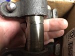
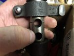
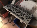
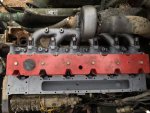
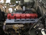
Buy all of the hold down bolts too, they stretch when rocker shafts break. Make sure you loosen and back the valve adjuster screws out. A heads up, the torque to yield method is ONLY used if you have the TTY head bolts. Using this method on non TTY bolts will result in broken head bolts. If you need help doing the overhead, PM me. I'd hate to see the same thing happen. While you had the front off I hope you verified the cam/crank timing. If not, since you still don't know WHY all these issues started, it would be a good thing to look at.
Thanks for the heads up Will, I’ll be sure to add those bolts to my list as well then. As for the TTY bolts, yes I have them, they are stamped as much on the top of them, I also followed the QS manual per my application, post-1991 with used bolts. I know I didn’t get into much detail here, but I covered more detail in my YouTube video. Yes, the cam/crank are timed correctly to each other, I verified that when I was retiming the injection pump. I hate to say it, but this may be one of those few times where we don’t know why something failed (in this case, why the rocker bolts came loose in the first place)
Mos,
It looks great. It is easy for us to throw bolts and wrenches at you from our arm chairs while you work on it and we don't. Not a lot of people here have deep dove into the 8.3's, so this is interesting. They are usually pretty robust engines, and yours has some pretty unique failures, so as Will said, try your best to figure out what caused it so we (you) are not doing this again 4 months from now. I would guess the only way a rocker shaft could fracture like that is from the bolts loosening up.
I know, nothing has been taken to heart. Unfortunately I know I’m one of the very few that have gone this deep into the motor, that’s why I’m trying my best to document everything really well so that someone else might have an easier time than I have when they do theirs. I would agree that the bolts coming loose are the only reason for the rover pivot shafts to break, but why did they come loose in the first place is what I’m wondering.
You said you advanced the injection timing? Don't go past 16 degrees (from the RV guys with the 8.3's). For the way your engine came apart, I'd probably just start with stock, since it is easy to set it that way with the factory push-pins (called pin timing). That is, if you believe the injection pump has not been messed with. Did you have a shop advance the pump internals, and to what degree? Then you can still pin time it (super easy to do). Make sure your tapered interface for the injection pump gear was completely free of grease/oil, they are known to slip if even a small amount of anything slippery on the tapered pump shaft or mating tapered gear bore.
I can’t say I know the exact timing angle now. Like I said above, I go into more detail in the video, but I followed the instructions of one of the pump veterans when I called to ask about retiming the pump. I’m 99.9% sure this pump hadn’t been adjusted by anyone prior to me, it still held gutless like the rest that I had drive when I was still in the service. I don’t have the pin for my pump and it seems to be a difficult bugger to find. Yes, no worries, the tapered shaft was clean as a whistle, as well as the pump gear.
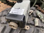
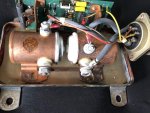
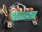
PCB looks hot in 2 areas of the board. It should not have caused engine failure though, it really only controls dash power and crank signal to starter. The circuit board on it is just to prevent re-engagement of the starter once the engine is running. Not all PCB's have it. This is done by detecting AC voltage at the alternator (before the rectifier) or oil pressure. I see you also have the fuel pressure sending unit atop your mechanical lift pump. That is usually just for the diagnostic tool, kind of useless. Watch that area for fuel leaks, it is a known issue. OK to remove sensor and cap.
Yes, there are two spots that have seen some heat on that PCB, but nothing to the point of failure. One is a resistor right next to a couple of MOSFETs and the other is on a pin for a diode. I still need to verify a few places on the PCB to make sure it is still functional, but now I’m pretty sure that this box wasn’t the point of failure in the electrical system. No dash power and no cranking power is the reason I automatically thought it was this box, especially with the fact that they are known to fail when the voltage regulator fails in the alternator.
Thanks for the heads up on the fuel pressure sensor, if it starts to leak I’ll be sure to do that.
If anyone has copies of the -10 manuals, or wiring diagrams, please let me know. I’ve looked, but I’m having difficulty finding anything.
