• Steel Soldiers now has a few new forums, read more about it at: New Munitions Forums!

  • Microsoft MSN, Live, Hotmail, Outlook email users may not be receiving emails. We are working to resolve this issue. Please add support@steelsoldiers.com to your trusted contacts.

802A & main utility entrance panel ground / neutral bonding question

Smithsonite

Member
23
52
13
Location
Central MA
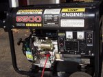
Just began my install of my 802A for automatic standby use. Have some questions ...

I learned about this topic when I installed a portable diesel generator for automatic standby use at my dad's place last year - the fact that neutral / ground can only be bonded in ONE location, or else breakers will not trip. Also found out that there shouldn't be more than one ground rod in the ground, either. The generator at dad's (A Kubota GL7000) had a jumper connecting neutral to ground in the gen head, so I removed that, creating a floating neutral. Wiring connected the gen neutral & ground to the main panel & transfer switch in the proper locations. All is working well there.

I'm not an electrician, but I have a fairly solid understanding of how 2-pole household power works. My house seems odd. Every main panel I've ever seen has had an intermixing of neutrals and grounds. Here, we had a 200A main panel installed 19 years ago where they separated the neutral and ground completely. This is where my question / confusion comes in.

So, since there is no connection between neutral & ground in my main, nor any other panel, I'm thinking I can leave the bonding bar in place on my 802A, and things will be fine. The only thing here is I have a sub-panel in my barn that also has separated neutrals and grounds (The neutral in the sub connects to the main panel's neutral), but has a ground rod below the panel. My main panel also has a ground rod, along with another ground to the copper plumbing in the house. Are these 2 (Or technically 3, since we have well water) grounding points going to be an issue?

The other thing I was thinking about ... and I don't know if I'm correct or not ... but my thinking is that since the grounds and neutrals are separated in my main panel, in the event of a lightning strike to a utility pole, everything in my house would fry. I was thinking if I connected a large jump wire from neutral to ground in the main panel, that would allow that current to go to ground, vs. cooking everything I own. Not sure if my thinking is right on that.

That brings me to my 2nd question: Should I leave everything be, or remove the bonding bar in the 802A & instead bond neutral / ground in my main panel?

Getting a headache trying to figure all of this out. Thanks in advance!
 
Last edited:

Smithsonite

Member
23
52
13
Location
Central MA
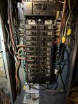
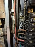
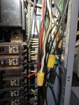
I can physically see they are not connected. Each bus bar has either neutral, or ground connected, but not both.

There's a heavier gauge wire that comes out of the ground bus, and runs across the other side of the basement to a rod in the concrete / fieldstone which is pounded into the ground. I can't show that since it's buried behind 600 lbs. of coal bags stacked up right now. Another goes to the copper plumbing.

Another ground rod I forgot about is just outside at the meter.

The ground rod for the sub panel is pounded into the ground just below the panel. That's about 40' away from the main panel in a separate building.

IMG_0549.jpeg

IMG_0550.jpeg

IMG_0551.jpeg
 

fb40dash5

Active member
Steel Soldiers Supporter
102
159
43
Location
MD
[I'm not an electrician] but I'm pretty OK at it.

Step #1 for me would be to ohm out between the two bars. They're separate bars, yes, but they may be interconnected by the panel housing itself. My guess is that you'd find very low/no resistance? (Meaning that there's an insulator or something that would be installed to un-bond the bars, and it's not installed)
 

DieselAddict

Well-known member
Steel Soldiers Supporter
2,532
2,059
113
Location
Efland, NC
I expect they are bonded in the main panel. Depending on the panel design there is a bonding screw that would be put in the neutral bar that will connect it to the frame of the panel. You won't necessarily see a jumper between the neutral and the ground buss bars.
 

Smithsonite

Member
23
52
13
Location
Central MA
Much appreciated as always, fellas. You guys were right! Low ohms between the bars, not only in the main panel, but also in the new transfer switch that isn't fully hooked up yet. Learn something new every day! I figured with the ground bus mounted direct to the panel, and the neutral bus mounted on plastic (As if it was insulated from the panel), they had to be separate. Makes me wonder why the neutral and ground have to be separated, if they're just connected anyway? Makes no sense to me!

Guess I'll be removing that bonding bar. Thanks again!
 

fb40dash5

Active member
Steel Soldiers Supporter
102
159
43
Location
MD
Makes me wonder why the neutral and ground have to be separated, if they're just connected anyway? Makes no sense to me!
It's a kinda hard concept to grasp & I had a rough time with it myself.

The gist of it is that while your ground is... grounded... the neutral eventually goes to ground, but it doesn't always just go to ground. Having your neutral & ground tied together in one place is good... but having them tied together in >1 places means that electricity flowing on your neutral between those points could also flow on your ground. And that's no bueno, because the ground isn't always insulated, and you have, for example, metal enclosures that are grounded... a ground loop could mean that a metal outlet box could have electricity flowing through it.

That's about the best I can convey my understanding, anyway... I didn't have the firmest grasp on it myself honestly & it's been about a year since I've needed to know it.
 

Jeepadict

Well-known member
477
706
93
Location
Round Mountain, NV
While I'm not an Electrician, I'm staying at a Holiday Inn Express next week. This is my best understanding, no promises...YMMV.

I went down this same rabbit hole when I first got my 802...took a while for everything to marinate into the ol' noggin. My greatest emphasis in my learning curve is this: the Ground and Neutral bond is to ONLY be installed at "the first disconnect means"...this translates to the first main panel fed from the utility (Telcom calls this the demarcation point) where your wires meet their wires and the big service disconnect is found. A bond found anywhere else in the system is bad news bears!

So here's the rub: providing that you have a newer structure with a 3rd wire Earth Ground, the earth ground exists to give an alternate/emergency return path for the AC current should there be a malfunction in an electrical device or the Neutral wire leg of any individual circuit. If a device allows for stray current or there's an open Neutral, the ground leg will act like a neutral to carry the return back to the first disconnect means where it would then follow the bond to the utility Neutral to allow the juice to get back to flowing like it should. The earth ground rod simply gives any random rogue energy demons a less resistive path to ground than your body. Now the reason there is to be ONLY ONE BOND: if there were ever to be stray voltage on the ground leg and there's more than one bond, it would then have an extra freeway to drive on to complete its circuit and ultimately energizing the ground leg...that extra freeway means there's no chance for fault protection overload (tripping a breaker) and bad stuff like fires start from overcooked wires. There's also rules about how many earth ground rods, how deep they need to be, and how far apart they need to be if there's going to be more than one...but my brain started to hurt at that point.

If there's ever any question or doubt about the configuration of any panel bond, invite the most reputable Electrician who is licensed and bonded with impeccable reviews for a visit to your home for an inspection. Let him double check what ever you have set for your generator while he's there! The piece of mind that comes from a competent professional will only cost you an hour of labor and a service call charge...that's money well spent in my book!
 

Smithsonite

Member
23
52
13
Location
Central MA
I appreciate the insight! Yeah, the stuff can make your brain hurt, especially when government gets involved and starts writing a 1,000 page novel on what can and can't be done.

So far, so good. When I was hooking up my coal boiler for the season, I tried to do it live, and arced my screwdriver out on the side of the aquastat case. BANG! Big flash, breaker tripped, so that's a good thing. Hell of a way to test it! :ROFLMAO: Guess I'm not as steady as I used to be!
 

2Pbfeet

Well-known member
433
772
93
Location
Mt. Hamilton, CA
While I'm not an Electrician, I'm staying at a Holiday Inn Express next week. This is my best understanding, no promises...YMMV.

I went down this same rabbit hole when I first got my 802...took a while for everything to marinate into the ol' noggin. My greatest emphasis in my learning curve is this: the Ground and Neutral bond is to ONLY be installed at "the first disconnect means"...this translates to the first main panel fed from the utility (Telcom calls this the demarcation point) where your wires meet their wires and the big service disconnect is found. A bond found anywhere else in the system is bad news bears!

So here's the rub: providing that you have a newer structure with a 3rd wire Earth Ground, the earth ground exists to give an alternate/emergency return path for the AC current should there be a malfunction in an electrical device or the Neutral wire leg of any individual circuit. If a device allows for stray current or there's an open Neutral, the ground leg will act like a neutral to carry the return back to the first disconnect means where it would then follow the bond to the utility Neutral to allow the juice to get back to flowing like it should. The earth ground rod simply gives any random rogue energy demons a less resistive path to ground than your body. Now the reason there is to be ONLY ONE BOND: if there were ever to be stray voltage on the ground leg and there's more than one bond, it would then have an extra freeway to drive on to complete its circuit and ultimately energizing the ground leg...that extra freeway means there's no chance for fault protection overload (tripping a breaker) and bad stuff like fires start from overcooked wires. There's also rules about how many earth ground rods, how deep they need to be, and how far apart they need to be if there's going to be more than one...but my brain started to hurt at that point.

If there's ever any question or doubt about the configuration of any panel bond, invite the most reputable Electrician who is licensed and bonded with impeccable reviews for a visit to your home for an inspection. Let him double check what ever you have set for your generator while he's there! The piece of mind that comes from a competent professional will only cost you an hour of labor and a service call charge...that's money well spent in my book!
Hey, I'm staying at a Holiday Inn next week, too! :ROFLMAO:

I struggle with the NEC bonding code(s) for a variety of reasons, probably because I don't have the entire code memorized and thought through. Nevertheless, having an extra path for current isn't going to cook wires that weren't going to cook in the first place. When a hot shorts to ground, the breaker on the hot is what will interrupt the circuit. Having two parallel paths reduces the resistance by a factor of two (+/-), so in principle the current through the hot will increase faster, and trip sooner.

Bonding neutral to ground at a generator would put stray / residual / imbalanced voltage from the neutral onto the chassis/frame of the generator, but it would be on the order of a few volts, tops before applying the generator ground, if the generator is attached to a building ground. (V=IR, and all that) If the house ground goes away, that is different, and if the generator has no ground of its own, very different.

My take away is always, always have a working ground attached to your generator. (And follow the military recommendations to water / and perhaps salt your ground zone.)

I'm still waiting for a coherent explanation of why utility transformers are allowed a ground on their neutral feeding a house, and generators aren't. I have reached out a number of times elsewhere for an explanation. Still waiting.

There are various rules that kick in at 5kW and 15kW.

All the best,

2Pbfeet
 

Smithsonite

Member
23
52
13
Location
Central MA
Yeah, linemen get a different set of rules than the rest of us, lol.

My very first generator I bought at a Cummins Tool sale - was like a roaming Harbor Freight store that hit all the sportsmen's clubs and VFW halls a few times per year. They had a very chinese generator there for cheap, since it fell off the loading dock. The tank was bashed in up top, and the generator & a couple engine mounts had busted off the housing. When I got home, I put my hand over the filler hole, and blasted it with 135 PSI of compressed air. BAM! Popped the tank out, and got an extra couple gallons to boot due to its now rounded shape.

The unit didn't have a 220V outlet (Was labeled for one, but the panel was blank above it), so I found the 2 hot leads, bought one at the hardware store, drilled the hole, and mounted it in the front panel. Worked great! That is ... until there was an unbalanced load on either leg.

When the load got too imbalanced - say pulling 1kW more on one leg than the other, the leg with the least current flashed up to near 200V! My lights got REAAAL BRIGHT!! When I opened my fridge, it looked like a portal into Heaven! :ROFLMAO: Anything chinese in the house at the time went up in smoke - the Kidde motion detector on the porch light, the Hampton Bay (Home Depot brand) ceiling fan's ballast fried, and the Walmart power strip also cooked. Circuit board was black when I took it apart!

That was fun, hahaha! I never un-bonded the neutral and ground in the generator, and the set itself wasn't grounded ... but there was something goofy going on with the neutral there, I suspect.

03D386D8-C174-4943-A1A9-B419C63BFA8C_1_105_c.jpeg

2FD36FA5-3E93-4139-99DE-9C62C5EB256B_1_105_c.jpeg
 

Mainsail

Well-known member
Steel Soldiers Supporter
1,502
1,676
113
Location
Puget Sound, WA
About 80% of this thread goes right over my head - apologies for what may be some ignorant questions...

The electrician wired my 802 to my panel, but didn't seem too concerned about the ground lug at the generator. I was told that the generator should be grounded, and was dangerous without it. I passed that to the electrician who ran a bare copper wire from the ground lug on the genset to the house ground rod, a distance of about six feet or so. That bare copper wire is a few inches under the dirt, and attaches to the house ground rod with a clamp.

The 802 is in what I will call standard configuration - I didn't add or take away any connections at the lugs, so whatever is "normal" there is the configuration.

Does my 802 need its own ground rod? Anything I pound into the ground is only going to be 6 - 10 feet from the house ground rod, so does it matter?
Are the N and G tied together at the generator in normal configuration? Do I need to untie them?

I'm not home right now, but the photo below shows what I remember my connections look like, except I have a bare copper wire from the GND lug to the house ground as mentioned.

1701785355589.png
 

Ray70

Well-known member
2,592
5,907
113
Location
West greenwich/RI
See the brass strip vertically near the bottom right corner of the terminal lug board, that strip is bonding neutral to ground in that picture.
Remove that bar to separate neutral and ground.
My understanding has always been that when connecting a generator ( or a sub panel ) to your main panel, the generator should be unbonded and you should be running 4 wires ( 2 hots, a neutral and a ground ) back to the main panel.
Your main panel should be the only place where neutral and ground are bonded together as well as connected to your ground rod or copper water line.
 

Smithsonite

Member
23
52
13
Location
Central MA
Ray is correct. No need for a ground rod at the generator. That ground lug should be connected to a wire that grounds with the main panel in the house, which is what it sounds like has been done (Although not pictured).
 
Top