• Steel Soldiers now has a few new forums, read more about it at: New Munitions Forums!

  • Microsoft MSN, Live, Hotmail, Outlook email users may not be receiving emails. We are working to resolve this issue. Please add support@steelsoldiers.com to your trusted contacts.

Advice needed - new guy with MEP004A

Back-in-Black

Well-known member
296
277
63
Location
Louisiana
Not disagreeing, just want to know because I hate not knowing exactly what I'm doing with stuff like this.

I will want to get with you on governor settings for sure. I haven't actually picked out or ordered an actuator for the throttle but this thing (DGC) will control the actuator to keep RPM as constant as possible using the input from the MPU. Appears to monitor droop, and such and has an option to enable "load control" which I'm guessing will run up the throttle as the current draw (load) increases.
 

Back-in-Black

Well-known member
296
277
63
Location
Louisiana
Not much to report lately. Decided to rent a large sandblaster and compressor and just do the blasting myself. Waiting for better weather for that project - might be waiting a while this time of year around here.

Drilled out and re-tapped the 7 screws holding the convenience receptacle assembly on and together. Had to grind the heads of the old screws off the get it apart / off.

Ordered a bunch of stainless steel bolts, nuts and washers. The case will be reassembled with all SS hardware. Don't want zinc hardware rusting all over my freshly painted MEP.

Started working on the wiring diagram in AutoCAD. Didn't get real far, really just the DGC with all connections and labels.

schematic v1.0.PNG
 

Back-in-Black

Well-known member
296
277
63
Location
Louisiana
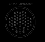
I dug all thru the TMs and spent hours searching the internet for a "pin-out" diagram of the big connector that goes into the instrument enclosure. Never found one for that exact connector so I spent some time last night doing it in CAD. Figured I'd share to anyone who would like it.

37 pin connector.PNG

edit: By the way, this is the "back" of the connector mounted to the instrument enclosure. Looking at it from the inside of the instrument enclosure. Obviously left and right "flip" when you look at it from the other side - where the connector screws on....

And a correction..... this is actually a 47 pin connector -40 small pins and 7 large pins. Been a while since I did all the digging and counting so I goofed up calling it a 37 pin connector.
 
Last edited:

Back-in-Black

Well-known member
296
277
63
Location
Louisiana
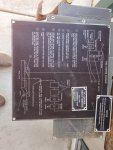
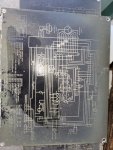
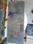
Also, as I posted earlier, I removed all the aluminum schematics and tags from the acoustic enclosure panels. There's no "restoring" this generator to anything near "factory condition" and these tags are pretty much useless on this particular MEP because it's been so heavily modified. So if anyone wants these, they're free to a good home. Some yahoo got some of them pretty good with over-spray but I think they'll clean up pretty well.

20211231_161824.jpg

20211231_161851.jpg

20211231_161855.jpg

20211231_161905.jpg
 

Guyfang

Moderator
Staff member
Moderator
16,696
23,904
113
Location
Burgkunstadt, Germany
All you have to do is look in the TM. The J1/P1 cable goes to the Special Relay box. There is on the schematics, at least twice if not three times, all the info as to what wire goes where. Then in the -34 Tm its shown again.
 

Back-in-Black

Well-known member
296
277
63
Location
Louisiana
I looked and looked but obviously not in the right place.

I drew it out mostly because I wanted it as part of the full schematic drawing I will be doing for this Frankenstein MEP.
 

Guyfang

Moderator
Staff member
Moderator
16,696
23,904
113
Location
Burgkunstadt, Germany
The control cube is A3
FO-1. AC and DC, 15 and 30 KW, 50/60 and 400 Hz,
Precise and Utility, Wiring Diagram, Dwg. No. 72-2205
(Sheet 4 of 4)

The S/P Relay box is A27
FO-1. AC and DC, 15 and 30 KW, 50/60 and 400 Hz, Precise and Utility, Wiring Diagram, Drawing No. 72-2205
(Sheet 3 of 4)
 

Back-in-Black

Well-known member
296
277
63
Location
Louisiana
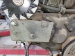
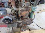
Pulled the small round timing cover off the motor and made a new gasket for it. The gasket was in pretty bad shape when I pulled it apart to rebuild the injection pump and I noticed what looked like a little fresh oil under it on the big timing cover when I pulled the motor off of the skids. One leak / potential leak fixed.

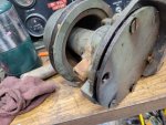
Pulled the water pump off and ordered the rebuild kit for it. Been bouncing this around in my head for weeks and I just couldn't see putting all this back together with a water pump that's likely to start leaking 3 days after I fill it with water. Not a job I wanted to do (rebuilding a water pump) but it's certainly a lot easier right now with the motor sitting on blocks. I already saw water dripping out of the weep hole a few weeks ago so I'm pretty sure this is the right thing to do.

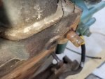
The nipple sticking out of the block for the bypass hose is looking pretty rough. Pretty sure it's just a short piece of 1/2" pipe threaded into the block. Will stop at the hardware store and get a 6" long galvanized nipple, cut it to length and replace the old one.

Also spent 20 minutes with a rat tail file on the crank pulley. It was pretty rough with rust from sitting all those years and I didn't want it tearing up fan belts.

20220101_092238.jpg

20220101_111007.jpg

20220101_112850.jpg

20220101_112854.jpg
 

Back-in-Black

Well-known member
296
277
63
Location
Louisiana
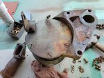
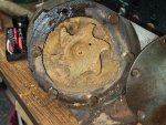
Well, after a week of soaking with penetrating oil I got the screws holding the water pump backing plate loose. Still had to use the old impact screwdriver and beat on them pretty good. Actually, had to heat up one of them with a torch and still had to beat on it pretty good.

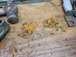
The crap in the picture all came out of the pump's water passages after beating on it.\

Still waiting on good enough weather to do the sandblasting.

20220108_184151.jpg

20220108_184228.jpg
 

Back-in-Black

Well-known member
296
277
63
Location
Louisiana
OK, got a question:

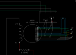
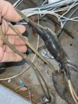
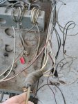
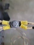
I went out and traced / documented the 12 leads from the main alternator (see below). Then I cut open the big blobs of weather tape to see what they had actually done when they rewired this thing. Pretty poor! They crimped ring terminals on the ends of the wires and then bolted the ring terminals together to complete the circuit(s). Then they wrapped the whole mess with 3M weather tape. What a mess!

Well, I cut all that crap off - I plan to bolt some terminal lugs onto the relay table (4 of them) and land the 4 circuits on those.

My question is; they left LOTS of slack in some of the wires (particularly T1, T6, T7 & T12) - LOTS of slack and it makes for a nice wiring rat nest. Is there any reason I can't trim the main alternator wires to the lengths that I need them to make for a neater end product????

MAIN ALTERNATOR SCHEMATIC.PNG

20211219_160823.jpg

20211219_160757.jpg

20220109_151808.jpg


Planning to use something like this, only with an insulated cover, to replace the current, mid-air mess.

terminal lugs.PNG
 

Attachments

Last edited:

Back-in-Black

Well-known member
296
277
63
Location
Louisiana
Got the pulley off the water pump earlier this evening. Had to use an impact wrench on the puller. That sucker is ON there! Don't really think it was so tuff because stuff was rusty and such. I think it's just a really tight interference fit.

Vibrating the pump with the impact resulted in another pile of rust on my work bench. I think I'm gonna get it all apart and blast it before I reassemble. There's a lot of scale inside it and I've tried this and that to break it loose but each time I think I got most of it, I end up with another pile of rust out of it.

I'm guessing the inside of my engine block probably looks similar.... Guess I'll try flushing it when I get it all back together.

20220109_193100.jpg
 

Scoobyshep

Well-known member
1,102
1,440
113
Location
Florida
impacts on gear pullers (well gear pullers in general) have their own hazard. I had a coworker loose an eye to one using an impact.

Next time try this, Load the gear puller until tight, apply heat to the item being pulled and tap with a hammer. when the gear puller loosens tighten and repeat. this accomplishes the same goal without excessive strain on the puller.


Either way, glad you were able to get it off without much issue, it does look crunchy.
 

Back-in-Black

Well-known member
296
277
63
Location
Louisiana
Yeah, I tried the heat thing before resorting to the impact. Left it overnight as tight as I could get it by hand. Temp the next morning was about 32F. Used a torch on the pulley hoping it would do the trick with the shaft close to 32F. Never budged a micron. Got the pulley up to about 200F, (laser thermometer) it never budged.

So I took a trip to the hardware store and bought 2, grade 8 bolts for the puller and screwed them in as deep as they would go. I was afraid that I'd pull the threads out of the hole or off the bolts..

One of the biggest problems to doing it by hand was trying to hold the pulley still while cranking on the puller. Couldn't get it in the vise w/o screwing up the belt groove.

All this after I had it soaked with penetrating oil for about a week.

My impact is old and it never was the strongest on the planet. I think I bought it about 40 years ago. It struggled the whole way off.
 

Mullaney

Well-known member
Steel Soldiers Supporter
Supporting Vendor
7,709
19,749
113
Location
Charlotte NC
Yeah, I tried the heat thing before resorting to the impact. Left it overnight as tight as I could get it by hand. Temp the next morning was about 32F. Used a torch on the pulley hoping it would do the trick with the shaft close to 32F. Never budged a micron. Got the pulley up to about 200F, (laser thermometer) it never budged.

So I took a trip to the hardware store and bought 2, grade 8 bolts for the puller and screwed them in as deep as they would go. I was afraid that I'd pull the threads out of the hole or off the bolts..

One of the biggest problems to doing it by hand was trying to hold the pulley still while cranking on the puller. Couldn't get it in the vise w/o screwing up the belt groove.

All this after I had it soaked with penetrating oil for about a week.

My impact is old and it never was the strongest on the planet. I think I bought it about 40 years ago. It struggled the whole way off.
.
Safety Glasses or a Shield or maybe BOTH could be in order using an impact on a puller.

Thing is, we all just wanna get the job done and walking over to the bench for safety glasses is a pain...
Having both eyes though would make that trip across the room would be worth your time.
 

Back-in-Black

Well-known member
296
277
63
Location
Louisiana
I will admit that I did not use a shield or safety glasses while pulling the pulley. Just did not occur to me, even though both glasses and shield were less than 4' away from where I was working. Never experienced or even heard of something like that happening using a puller but I have now!

Spent the afternoon cleaning up the relay table so I can start mounting my bus bars for generator winding outputs and generally cleaning up that part of the wiring. I went with bus bars because they were rated at 150 amps and have covers. They should be here tomorrow.


20220112_175725.jpg

20220112_180522.jpg
 

Back-in-Black

Well-known member
296
277
63
Location
Louisiana
In a bit of a conundrum about the engine valve cover. 90% of the paint has flaked off of it and the bare metal is rusting, I'm afraid to pull the valve cover because sure as sunshine, the gasket is going to fall apart into 20+ pieces the minute I pull it apart. I can buy an entire engine gasket set for ~ $450 but that would be a bit retarded for a valve cover gasket. I also think that's a bit too much and too big a gasket to attempt by hand. There is a company in town that can cut gaskets on a CNC machine if you bring them a pattern... Sounds expensive. Guess I'll have to call them and ask.
 
Top
AdBlock Detected

We get it, advertisements are annoying!

Sure, ad-blocking software does a great job at blocking ads, but it also blocks useful features of our website like our supporting vendors. Their ads help keep Steel Soldiers going. Please consider disabling your ad blockers for the site. Thanks!

I've Disabled AdBlock
No Thanks