• Steel Soldiers now has a few new forums, read more about it at: New Munitions Forums!

  • Microsoft MSN, Live, Hotmail, Outlook email users may not be receiving emails. We are working to resolve this issue. Please add support@steelsoldiers.com to your trusted contacts.

Advice needed - new guy with MEP004A

Back-in-Black

Well-known member
296
277
63
Location
Louisiana
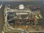
Well, I found the short - sort of. It's the panel lights. Turn them off and the short goes away. This thing sucks to trace wires on. They're all the same color (or damn near anyway). I must have cut 100 tie wraps off and pulled 5' of wire loom loose. To top it off, the guys who re-did this thing cut wires everywhere and spliced in different color wires in the middle of nowhere. Anyway, was able to trace the short to the panel lights but didn't go any further trying to locate that problem... just turned off the panel light switch. Will trace it down all the way later.

The other problem is that it won't even bump the starter. I'm not totally sure yet exactly how the starter is wired up but I think it all goes back to one of 2 solid state boards that were added. I traced the starter solenoid wire back into the instrument panel and to what's labeled as "starter relay". Which makes sense. The coil activation wire for that relay goes back to this solid state board... so does at least one wire from the Off/ Auto / Manual toggle. Also, 2 wires to one of the barrier strips were cut about a foot outside the control panel. I traced the wires on the opposite side of the strip from the cut wire and it also goes back to the same solid state board. I'm pretty sure that the cut wires were shore power for the sense function /auto start and that this board controls all that. That's why the wires were cut - when they pulled it out they had to cut it loose from the building. I gotta get some wire labels before I take that board out for inspection and to try to determine who made it, etc.

Question: Should I be able to short 24 volts from the + connection from the battery at the starter to the "start lug" of the starter solenoid and at least make sure the solenoid and starter work???


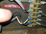
The bottom black and white wires in this pic are the ones that were cut just outside the back of the control panel. The blue wires run over to the solid state board.
20210929_141025.jpg

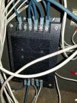
This is the board that seems to control start and shore power sense functions. I traced 24V supply to one of the top lugs. The shore power hot to another and the Off/Manual/Auto toggle to another.

20210927_101747.jpg

20210927_101720.jpg
 

Scoobyshep

Well-known member
1,090
1,403
113
Location
Florida
Well, I found the short - sort of. It's the panel lights. Turn them off and the short goes away. This thing sucks to trace wires on. They're all the same color (or damn near anyway). I must have cut 100 tie wraps off and pulled 5' of wire loom loose. To top it off, the guys who re-did this thing cut wires everywhere and spliced in different color wires in the middle of nowhere. Anyway, was able to trace the short to the panel lights but didn't go any further trying to locate that problem... just turned off the panel light switch. Will trace it down all the way later.

The other problem is that it won't even bump the starter. I'm not totally sure yet exactly how the starter is wired up but I think it all goes back to one of 2 solid state boards that were added. I traced the starter solenoid wire back into the instrument panel and to what's labeled as "starter relay". Which makes sense. The coil activation wire for that relay goes back to this solid state board... so does at least one wire from the Off/ Auto / Manual toggle. Also, 2 wires to one of the barrier strips were cut about a foot outside the control panel. I traced the wires on the opposite side of the strip from the cut wire and it also goes back to the same solid state board. I'm pretty sure that the cut wires were shore power for the sense function /auto start and that this board controls all that. That's why the wires were cut - when they pulled it out they had to cut it loose from the building. I gotta get some wire labels before I take that board out for inspection and to try to determine who made it, etc.

Question: Should I be able to short 24 volts from the + connection from the battery at the starter to the "start lug" of the starter solenoid and at least make sure the solenoid and starter work???


The bottom black and white wires in this pic are the ones that were cut just outside the back of the control panel. The blue wires run over to the solid state board.
View attachment 847863

This is the board that seems to control start and shore power sense functions. I traced 24V supply to one of the top lugs. The shore power hot to another and the Off/Manual/Auto toggle to another.

View attachment 847864

View attachment 847865
24 volt + to the solenoid (trigger wire) on the starter should make the starter run

Sent from my SM-G973U using Tapatalk
 

Back-in-Black

Well-known member
296
277
63
Location
Louisiana
Been digging around reading. Forgive my ignorance but this is my first dive into generators and their controls.

The board that does all the start / monitoring functions is apparently an "Auto Start Control Module". Looks like I can get one for anywhere from ~$250 - ~$500 or so. Was looking at Deep Sea Electronics - mainly because they were the first ones coming up in my web searches. Think their DSE4610 is probably the model I would need. I'll need t ask some questions here before I do anything.

The other board is apparently an AVR (Automatic Voltage Regulator).

I need to get some wire labels and start building a schematic for this thing.

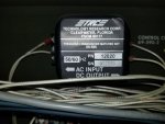
Can anyone tell me what this does?
20210927_101728.jpg
 
Last edited:

Back-in-Black

Well-known member
296
277
63
Location
Louisiana
That converts a 120 VAC signal to a VDC signal, to drive the Frequency meter.

I wish you luck in the troubleshooting and repairing this set.

Actually, after digging around in the wiring and reading on the web last night, I am more optimistic than before. I'll have to trace and label all the wires and create a schematic for it but it looks like if I take things like oil pressure, temp and such and feed them into a new controller, I can control start, stop, fuel pumps on/off and such quite easily.

The question floating around in my head right now is can I get some sort of throttle actuator and electronically control RPM via the controller. Of course the first question on that front is do I need to? Will this thing stay close enough to 1800 RPM under varying loads to not worry about that? Cycling air conditioner compressors is the one that makes me think I might need to but I just don't know enough about this yet.

I also need to research into whether or not I also need to replace the automatic voltage regulator so it will interface with the controller board. I read some stuff last night that made me think that might be necessary. The new fangled controllers seem to pretty much cover all the necessary monitoring and control and even provide an LCD display so you can see things like leg voltage and possibly even frequency. They are also programmable via a laptop so you can setup stuff like activating fuel pumps and such via their analog output channels. I imagine that calibration for temp and oil pressure (if needed) might take some time and brain cells. Sort of like a purpose built PLC.
 

Scoobyshep

Well-known member
1,090
1,403
113
Location
Florida
Actually, after digging around in the wiring and reading on the web last night, I am more optimistic than before. I'll have to trace and label all the wires and create a schematic for it but it looks like if I take things like oil pressure, temp and such and feed them into a new controller, I can control start, stop, fuel pumps on/off and such quite easily.

The question floating around in my head right now is can I get some sort of throttle actuator and electronically control RPM via the controller. Of course the first question on that front is do I need to? Will this thing stay close enough to 1800 RPM under varying loads to not worry about that? Cycling air conditioner compressors is the one that makes me think I might need to but I just don't know enough about this yet.

I also need to research into whether or not I also need to replace the automatic voltage regulator so it will interface with the controller board. I read some stuff last night that made me think that might be necessary. The new fangled controllers seem to pretty much cover all the necessary monitoring and control and even provide an LCD display so you can see things like leg voltage and possibly even frequency. They are also programmable via a laptop so you can setup stuff like activating fuel pumps and such via their analog output channels. I imagine that calibration for temp and oil pressure (if needed) might take some time and brain cells. Sort of like a purpose built PLC.
I used an electronic actuator and frequency sensor with my plc to adjust frequency. Yes depending on the load the engine speed will droop.

Sent from my SM-G973U using Tapatalk
 

Back-in-Black

Well-known member
296
277
63
Location
Louisiana
Question: Anyone know what extractor tool I need to use to remove the pins / wires that are no longer used on the large connector going into the rear of the control panel??
 

Back-in-Black

Well-known member
296
277
63
Location
Louisiana
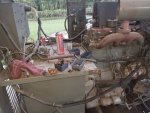
same picture above: There is a sensor screwed into the engine block right behind the injector pump. I cannot find it in the TMs but according to the TMs, I should have an oil pressure transmitter and an oil pressure switch over by the oil filter. I only see what looks to be a transmitter (4 wires). Is the one on this side of the motor the oil pressure switch?
 

Back-in-Black

Well-known member
296
277
63
Location
Louisiana
Progress:

I got most of the engine control and sensor wires mapped to the multi-pin connector on the back of the control housing. BTW, if anyone is interested I found out that this is a Bendix (bought out by Amphenol at some point) 36-7 connector (36 small pins and 7 large pins for a total of 42). Working on getting pin extractors (large and small pins) now. Will post info on that when I get it.

Next step will be identifying those same wires on the control side of that connector. Step after that will be tracing and identifying the main alternator wires. Then I will label each wire at each end and build a schematic for it.

I still need to figure out exactly what they did with the charging alternator. Looks like an older GM automobile alternator that they installed and wired in. There are some large, ceramic type resistors in that circuit - I think to drop the exciter voltage (for the charge alternator) down to 12 volts rather than 24? Gotta look at it closer and maybe draw it out because I'm not sure what the second large resistor is for yet....
 

Back-in-Black

Well-known member
296
277
63
Location
Louisiana
Update: Haven't really been able to spend any time on this project until tonight. I wired in 2 temporary toggle switches. One to provide 24 volts to the fuel pump and the IP solenoid. Another to provide 24V to the starter solenoid.

I turned on the fuel pump and cracked the bleeder on the secondary fuel filter and waited for the fuel to fill the water separator, the primary filter and the secondary filter... and waited, and waited, and waited some more. Cracked the petcock on the water sep. - yep a little fuel dribbling out. And waited some more. Finally I turned it off and disconnected the supply line from the pump at the water sep. and stuck the line in a clear bottle and turned the pump back on. Only getting a very small dribble of fuel. Found what looks like the exact same fuel pump on Amazon and ordered it. Supposed to be here Sunday.

Starter: I hit the switch to engage the starter solenoid and got a good, loud clunk a couple of times but no spinning starter. So I got my wrench back out and spun the motor over. It spins very easily so I went and hit the starter toggle again. Not even a click! This is what it did the first time I just tried touching a hot wire to the start lug on the solenoid. Guess I'll be taking the starter and solenoid apart this weekend to clean and lube everything.

In the meantime, I've done a little more on-line research. Got the model number of the Analog Voltage Controller and downloaded the manual for it. For right now, I am going with the theory that this part is still good and I'm just trying to get the engine going so I can confirm that. I know that the other solid state "box" that controls the engine and such is smoked - hence the rigged up fuel pump power and starter circuits.
 

Back-in-Black

Well-known member
296
277
63
Location
Louisiana
Crap! Found the problem with the fuel pump. The other day I was out there just tracing wires and such and saw this damn bug (bee / wasp looking thing) crawling into one of the fuel elbows I pulled off the fuel tank and had left laying in that tray on top of the generator. I immediately put bolts in the holes to plug them up. The damn bugs crawl into any small hole, lay an egg and plug the hole with mud or something. The next day I saw another one crawling out of a steel line still connected to the fuel tank. Damn bugs! Anyway, after making the above post, I got to thinking.... I wonder if one of those damn bugs built a nest in the supply line to the fuel pump? Pulled the end out of the 5 gallon diesel can and disconnected the other end from the fuel pump. sure enough, friggin bug larvae at the entrance to the fuel pump along with some mud or such. Blew the line out with the air hose and out comes more crap. Hooked it all back up and turned it back on. I have fuel at the IP now. About to go back out and pull the starter now. Had to come back to the house to cancel my $50 fuel pump order from Amazon.
 

Back-in-Black

Well-known member
296
277
63
Location
Louisiana
Bugs!

Pulled the starter. It was turning quite freely and the bendix also moved freely so I took apart the solenoid. Wow! Contact surfaces in PRETTY bad shape! Nice piece of work though - all silver plated copper. Anyway, cleaned all the contact surfaces real good and reassembled. Starter / solenoid now works like a charm.

Wish I could say the same for the injection pump. Got good fuel and pressure at the supply inlet. Got fuel at the top at the return lines (should there be fuel there when fuel hasn't reached the injectors yet?) but no fuel at all at the injectors. I've cracked a couple of the banjo bolts that feed the injector lines at the IP. Got fuel there but can't seem to get the pump primed or maybe it just ain't pumping. Dry as a bone up at the injector end. Heck, I even gave it a shot of ether and it ran for a minute or so but still no fuel at the injectors. I can hear the solenoid in the IP thunk when I power it up.

Anyone got and ideas or suggestions??
 

Back-in-Black

Well-known member
296
277
63
Location
Louisiana
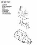
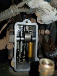
Question: What does the "shutdown arm" actually do? Is it supposed to move something down in there besides itself? I keep thinking that when I power the shutdown solenoid it's not really doing anything but moving this arm. The solenoid works. I've verified that. But I see nothing down in there that it could move- other than itself - and that doesn't appear that it would have any effect on fuel delivery. Can't get fuel to the injectors and I keep coming back to this. Am I in "permanent shutdown mode" because when I power the solenoid, it's not doing what it's supposed to????

#15 in the drawing.
inj pump exploded.PNG

20211005_181405.jpg
 

Back-in-Black

Well-known member
296
277
63
Location
Louisiana
Did some "googling" on the no fuel to injectors subject and then some checking. I see lots of small pieces of something at the bottom of the IP "bowl" that wasn't there before I added fuel and tried to start the motor. Also pulled out the check valve again and it had lots of crud in it too - after I cleaned it when guyfamg told me to. Some of it felt like rubber and some felt like rust. Looks like I need an IP rebuild. Working towards that now.

I hope I can get the motor going. As I stated in an earlier post, I feel more optimistic about this thing now than I originally did since I found that I can most probably "retro-fit" an easily acquired, modern PLC type controller to it. I'm pretty comfortable with that type stuff as I do that type of thing for a living. I've already got a controller and a throttle actuator picked out for it but just don't want to drop a lot of $ into it if all I have is a very large and HEAVY boat anchor.

Since I heard the motor run for a few seconds (ether), I am even more optimistic. Just have to address things like water leaks and such after I get the IP going.
 

Ray70

Well-known member
2,562
5,796
113
Location
West greenwich/RI
The shutdown solenoid presses against the linkage shown in the left side of your photo.
That moves the linkage towards the fuel inlet end of the IP, in turn rotating the fuel metering rod and shutting off fuel flow.
With the cover removed, if you manually move the fuel shut off lever ( which is probably tied back towards the fuel inlet with wire ) move it towards the front of the engine, that should essentially move the internal linkage the same way as the solenoid does.
If the linkage doesn't move and is stuck the the off position, that could be why you aren't getting fuel.

When you say you have fuel at the banjo bolts but not at injectors, are you getting timed spurts at the banjo bolts or is it just dripping a little when you loosen bolts?
 
Top
AdBlock Detected

We get it, advertisements are annoying!

Sure, ad-blocking software does a great job at blocking ads, but it also blocks useful features of our website like our supporting vendors. Their ads help keep Steel Soldiers going. Please consider disabling your ad blockers for the site. Thanks!

I've Disabled AdBlock
No Thanks