• Steel Soldiers now has a few new forums, read more about it at: New Munitions Forums!

  • Microsoft MSN, Live, Hotmail, Outlook email users may not be receiving emails. We are working to resolve this issue. Please add support@steelsoldiers.com to your trusted contacts.

Advice needed - new guy with MEP004A

Back-in-Black

Well-known member
296
277
63
Location
Louisiana
Sounds like you have already decided what you want to do for control system, but if things change, I wonder if this gen would be a good candidate for an SX-460 AVR?
I've used them a few times on different military gens and they have worked well every time.

Ok, this is a voltage regulator. I thought maybe you were talking about the "motor controller". The one that was already installed on this set is a Basler AVC63-4. Pretty sure it smoked because someone put 10 Amp slow blow fuses where they were supposed to be 6 Amp fast blow. One of the 10 Amp fuses was absolutely smoked. I never even looked at other AVRs because this one is still made (updated but same thing / model) and it was just too easy to get a direct replacement. That's what I ordered this weekend and should be here tomorrow. For now, the Basler thing will work (I hope) but if I have any problems with it I will order the Stamford one. BTW, apparently the SX460 has been discontinued and replaced by the AS440.

The "motor controller" I'm looking at is this: https://www.deepseaelectronics.com/genset/auto-mains-utility-failure-control-modules/dse4620

Anyway, this thing might not be the final product I buy but gotta do some more research before I commit to one or another.
 

Back-in-Black

Well-known member
296
277
63
Location
Louisiana
Will that work? spec sheet calls for a minimum of 15 ohms. 004 field winding is 2-4 ohms.

Ahhhhhhh, maybe you didn't see the part where the AVR / AVC is not controlling the field on the MEP. It's controlling the field on the Delco alternator and monitoring the output of the MEP (120, neutral). So basically what's going on here is that the Basler AVC is regulating the output of the MEP by regulating the field of the Delco. So if the MEP voltage out is low, the AVC increases the field of the Delco, which increases the output of the Delco, which increases the field of the MEP which raises the voltage out of the MEP.

Yeah, it took me a little while to get my head wrapped around that one..... But I have to admit, it's a pretty "elegant" solution.
 
Last edited:

Back-in-Black

Well-known member
296
277
63
Location
Louisiana
Wellllllllllllllllllllllllllllllllllll,

In a normal 004A, the S9-1 contacts are closed, (pins A&B) on start up. Those pins allow the starter solenoid to do its thing and the starter turns the engine. At a certain RPM, (look in the TM if you want to know) the S9-1 contacts reverse. Pins A&B open and drop the Starter solenoid out, and pins A&C close, and 24 volts goes to the main gen, excitation roter, to light off the main gen. At that point, you let go of of the start switch, and K6, (if I remember right) reverses contacts and allows the Volt Reg/static exciter to control the production of AC from the main gen. But the speed switch is not what controls the K6.

Spur Gear:


TEETH QUANTITY135

YOU ROCK!!!

Spur gear huh? I'd have never looked with that term. I actually just searched the TMs and still couldn't find "spur gear". THANK YOU for that one - saved me a lot of trouble!!!

So I'm guessing the initial exciting voltage comes from the batteries / 24 volt system on a normal MEP and the speed switch basically "controls" the relays that set all that in motion. There are only 2 relays left on this one - the 2 behind the control panel labeled "start" and "run".

I also just realized that the flash in this case is not a "flash" It's just a constant use of the Delco's output to supply field voltage to the MEP. The "flash" would be getting the Delco cranked up and producing voltage which I think the AVC will do.

You guys will hopefully excuse my rambling. A lot of it is just me "thinking out loud".
 
Last edited:

Guyfang

Moderator
Staff member
Moderator
16,671
23,836
113
Location
Burgkunstadt, Germany
Spur gear is the proper name for it. But normally its just called a ring gear. And, until I started snooping around, had never heard the term spur gear. I have the data for the rest of the spur gear also if you want it. But unless you are going to replace it, you should not need it.
 

Back-in-Black

Well-known member
296
277
63
Location
Louisiana
Hopefully I don't need anything but the number of teeth on it, which I now have thanks to you.

My AVC came n. Installed it. Still doesn't make power "natively" which I think is due to the alternator not making any power. If I put 24 volts from the batteries on the output of the alternator, I get about 94 volts AC between L1 and L0. So, I'm making power!!!! Going to drop the Delco at a local starter / alternator shop in the morning and he says he can have it ready in the afternoon - BUT, pretty sure this is not your everyday alternator so if he needs any parts for it, I doubt he has them in stock. We'll see.

Anyone got a clue how many VDC it takes on the field of the MEP to make 120 VAC?

I'm guessing that once the initial flash is done, an unmolested MEP robs some of the AC output and converts it to DC to run the field? I'm guessing that's what a lot of those capacitors I see n the TM are for?
 

Scoobyshep

Well-known member
1,090
1,403
113
Location
Florida
Hopefully I don't need anything but the number of teeth on it, which I now have thanks to you.

My AVC came n. Installed it. Still doesn't make power "natively" which I think is due to the alternator not making any power. If I put 24 volts from the batteries on the output of the alternator, I get about 94 volts AC between L1 and L0. So, I'm making power!!!! Going to drop the Delco at a local starter / alternator shop in the morning and he says he can have it ready in the afternoon - BUT, pretty sure this is not your everyday alternator so if he needs any parts for it, I doubt he has them in stock. We'll see.

Anyone got a clue how many VDC it takes on the field of the MEP to make 120 VAC?

I'm guessing that once the initial flash is done, an unmolested MEP robs some of the AC output and converts it to DC to run the field? I'm guessing that's what a lot of those capacitors I see n the TM are for?
On startup (flash) it borrows 24 vdc from battery to get the reaction going. after it takes the high voltage ac off the head and maintains the field. heres the tricky part, its an inverse reaction. as the AC goes up the DC field needs to go down (otherwise the AC will keep increasing) when the AC voltage goes down the field needs to go up to compensate. If memory serves (mind the cobwebs) it runs somewhere around 32 volts.

If it were me, I wouldnt try relying on the alternator to maintain the field. I would get an appropriately sized AVR and be done with it. you will still need a flash relay to kick off the head though.
 

Ray70

Well-known member
2,562
5,796
113
Location
West greenwich/RI
I agree with Scoobyshep. I don't trust that alternator setup, but maybe it's just because I'm not familiar with it.
Aftermarket AVR's can be had cheap.
That SX460 is still available ( Chinese knock off ) for $20 all over the internet.
You could probably buy 4 or 5 of them for less than the Delco rebuild will cost.
I know Scoobyshep mentioned the winding resistance may not be correct, but it may be worth further investigation.
I've used them on 002's 003's 016's and others, but never checked the resistance on any of them.
Possibly @KKlop could weigh in and give his advise as to if he thinks it might work?
 

Scoobyshep

Well-known member
1,090
1,403
113
Location
Florida
I agree with Scoobyshep. I don't trust that alternator setup, but maybe it's just because I'm not familiar with it.
Aftermarket AVR's can be had cheap.
That SX460 is still available ( Chinese knock off ) for $20 all over the internet.
You could probably buy 4 or 5 of them for less than the Delco rebuild will cost.
I know Scoobyshep mentioned the winding resistance may not be correct, but it may be worth further investigation.
I've used them on 002's 003's 016's and others, but never checked the resistance on any of them.
Possibly @KKlop could weigh in and give his advise as to if he thinks it might work?
I used one on a 005 and one (not your exact model but similar field ratings) didnt have the balls to keep the reaction going. I ended up using 3 of them and isolating them with rectifiers.

This was more of a need to replace so lets try project.
 

Back-in-Black

Well-known member
296
277
63
Location
Louisiana
So an AVR that can handle 2 to 4 ohms across the field connection? Wouldn't think that would be so hard to find. It'll pull the needed voltage from the main AC output and all I gotta do is give it a 24 VDC kick in the pants to get the process going?

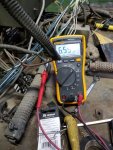
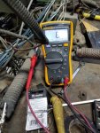
One thing I don't really understand about the current setup is the big, ceramic type resistor that's in-line between the alternator output and the field of the MEP. I've tested it and it shows 6 ohms. Then I put 24 VDC on it and the voltage on the other end drops to 6.5 VDC. I'm guessing that this is why I can't make more than ~90 VAC. Not real knowledgeable about why this is in the circuit and don't understand how a "current limiting" resistor limits the current without also limiting the voltage.

If I put a relay in to flash 24 VDC from the batteries, do I need to worry about a current limiting resistor for that too or can I just hook it straight up? Maybe a circuit breaker or fuse in-line between the 24VDC and the F+? All of this would certainly be very simple to wire up and once I get a motor controller, I can use it to operate the relay. For testing, I'll just use a toggle switch to activate the relay but for testing I could just use the toggle by itself. Pretty sure I have a DPDT relay floating around here somewhere - maybe in my truck.

20211117_170954.jpg

20211117_171034.jpg
 

kloppk

Well-known member
Steel Soldiers Supporter
2,129
3,495
113
Location
Pepperell, Massachusetts
.....Possibly @KKlop could weigh in and give his advise as to if he thinks it might work?
The SX460 won't work with the 004. The 004 Exciter Stator resistance spec is 4.5 to 5.5. ohms, nominally 5.0 ohms.
The lowest resistance exciter the SX460 can work with is 10 ohms or higher. It's doesn't have the current output needed to drive 5 ohm 004's Exciter Stator.
 

Scoobyshep

Well-known member
1,090
1,403
113
Location
Florida
Maybe I am looking in the wrong spot, but the -34 TM
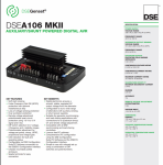
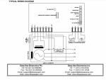
Same guys who make the motor controller I've been looking at. What do you guys think? Field 5-50 ohm.


View attachment 851009

View attachment 851010
I wouldnt, its too close to the bottom end rating.

Maybe I am looking in the wrong place, But the -34 TM page 1-9 calls out the Exciter rating resistance as 2.19 ohms.
 

Back-in-Black

Well-known member
296
277
63
Location
Louisiana
Maybe I am looking in the wrong spot, but the -34 TM

I wouldnt, its too close to the bottom end rating.

Maybe I am looking in the wrong place, But the -34 TM page 1-9 calls out the Exciter rating resistance as 2.19 ohms.

From the TM: Equipment Test of Field Flash Circuit Assuming the exciter stator winding resistance is correct (within 1 to 4 ohms)

I'm starting to see why they put the Delco in there - no one makes an AVR that will handle 4 ohms much less 2. Think I'll bring in the Delco in the morning.

And maybe that's why the 6 ohm ceramic resistor is in there - to get the field resistance up.
 
Last edited:

Back-in-Black

Well-known member
296
277
63
Location
Louisiana
BTW, found out that the particular connector they used to the control panel (37 pin) is a rubberized version and you cannot extract the pins. However, the same plug is made in a few different versions. They have letter designations. I think the type used OEM is an A type. Another type had solder cups.

Since I have so many cut wires, I decided I needed to clean mine up quite a bit. It's really hard to trace wires thru that connector. So I ordered a solder cup version for it. Should be here in a week or so.
 

Back-in-Black

Well-known member
296
277
63
Location
Louisiana
I can't tell - not very good with the TMs yet.

I got the solder type coming. I tried to get pins and an extractor for that plug. No luck and was told it was a weather proof connector and the pins were not extractable. Matters not as long as I have some way to clean it up. I bet half the wires on that plug are cut. I need to get rid of all those cut wires so I can clean this thing up. Can't stand working on a mess. Before this is all over I will do a full schematic on how it is wired. I almost certainly will rewire a good portion of it since they did such a messy job.
 

Guyfang

Moderator
Staff member
Moderator
16,671
23,836
113
Location
Burgkunstadt, Germany
The TM will not show you how to pull the pins. I unscrewed the plug end on the cable side, pulled the plastic cover down and simply pushed the pins out. After a while, I got the opposite pin, (female?) and used that to push them out. On the jack side, I seem to remember simply pushing the pins out with a needle nose. But thats been maybe 40 + years ago?
 
Top
AdBlock Detected

We get it, advertisements are annoying!

Sure, ad-blocking software does a great job at blocking ads, but it also blocks useful features of our website like our supporting vendors. Their ads help keep Steel Soldiers going. Please consider disabling your ad blockers for the site. Thanks!

I've Disabled AdBlock
No Thanks