• Steel Soldiers now has a few new forums, read more about it at: New Munitions Forums!

  • Microsoft MSN, Live, Hotmail, Outlook email users may not be receiving emails. We are working to resolve this issue. Please add support@steelsoldiers.com to your trusted contacts.

Advice needed - new guy with MEP004A

Back-in-Black

Well-known member
296
277
63
Location
Louisiana
Usually with that type connector, there is an extractor tool to push them out. I had one of my suppliers looking for pins and an extraction tool. Don't exist so I just went with the solder type. Since I don't have near 37 wires anymore, I could have gone with a different connector but decided that I didn't want to screw with different size body / hole thru the back of the control box and when I put it back together, I can skip pins to lighten up the density a bit. Right now, there's just too many wires in a very tight space.
 

jamawieb

Well-known member
1,437
556
113
Location
Ripley/TN
(9) MEP-004a or 005a voltage regulator | SteelSoldiers check out my most recent updated post. The 004 and 005 use the same electrical system. I finally pulled the entire VR/exciter box. I originally replaced the T2 transformer with a SP100MQMJ transformer and hooked it up. Worked well for a while then the large capacitors crapped out so I decided to finally remove everything and replace with a ADVR054 VR. That particular VR worked well with the single phase converted 005a I had. I have another unit that is used at 480v for a irrigation well. The T2 transformer failed and instead of messing with it again, I replaced the entire box with a ADVR054 but I had alot of unstable voltage at 480v. So I had a Marathon se350VR from a Drash HVAC unit and tried that one. It worked very well but would not generate without an external exciter. So I put a water proof push button beside the CB1; I took 24v off the CB1 to the push button and then from the button to F1 field terminal. I installed a 56 ohm resistor on the wire going from the button to F1 and I put a n5406 diode after the resistor so I wouldn't have reversing power go through the resistor or button. For safety I put the same diode in between the VR F1 and F1 terminal screw so the new external exciter would not feed into the VR. I also installed the push button on the unit with the ADVR054 because I went out to start it after a year and it would not generate. Installed the button to excite the field and poof, worked again. It lost the residual voltage to excite the VR field.
The reason I used the 56 ohm resistor is because that resistor is used in the 002a and 003a exciter board so I thought if it worked on those units, then it would work on the larger units. From limited research, most generators use 0-200ohms to generate so 56 ohms should work.
Hope this helps!
 

Back-in-Black

Well-known member
296
277
63
Location
Louisiana
(9) MEP-004a or 005a voltage regulator | SteelSoldiers check out my most recent updated post. The 004 and 005 use the same electrical system. I finally pulled the entire VR/exciter box. I originally replaced the T2 transformer with a SP100MQMJ transformer and hooked it up. Worked well for a while then the large capacitors crapped out so I decided to finally remove everything and replace with a ADVR054 VR. That particular VR worked well with the single phase converted 005a I had. I have another unit that is used at 480v for a irrigation well. The T2 transformer failed and instead of messing with it again, I replaced the entire box with a ADVR054 but I had alot of unstable voltage at 480v. So I had a Marathon se350VR from a Drash HVAC unit and tried that one. It worked very well but would not generate without an external exciter. So I put a water proof push button beside the CB1; I took 24v off the CB1 to the push button and then from the button to F1 field terminal. I installed a 56 ohm resistor on the wire going from the button to F1 and I put a n5406 diode after the resistor so I wouldn't have reversing power go through the resistor or button. For safety I put the same diode in between the VR F1 and F1 terminal screw so the new external exciter would not feed into the VR. I also installed the push button on the unit with the ADVR054 because I went out to start it after a year and it would not generate. Installed the button to excite the field and poof, worked again. It lost the residual voltage to excite the VR field.
The reason I used the 56 ohm resistor is because that resistor is used in the 002a and 003a exciter board so I thought if it worked on those units, then it would work on the larger units. From limited research, most generators use 0-200ohms to generate so 56 ohms should work.
Hope this helps!

Thank you for taking the time to post all that great info. I will dig into all that. Does the 56 ohm resistor generate a lot of heat? The little that I played with shoving 24V thru the 6 ohm resistor on this one, that thing got pretty hot. And that was after only a minute or so. Guess it really doesn't matter as long as it's well insulated from anything flammable.

Your pushbutton idea is pretty much what I was thinking about doing - I was was just going to automate my button as I'm after an auto start on power failure type set. The diode is a great idea!

And yes, after mulling on it for a while, the only resistance on a field coil would be the resistance of the copper wire over it's length. That doesn't make for a lot of resistance so 2 - 4 ohms I'm guessing is fairly normal unless something like a resistor is added.

Never fiddled with generators before but this is actually kind of fun.
 

jamawieb

Well-known member
1,437
556
113
Location
Ripley/TN
Thank you for taking the time to post all that great info. I will dig into all that. Does the 56 ohm resistor generate a lot of heat? The little that I played with shoving 24V thru the 6 ohm resistor on this one, that thing got pretty hot. And that was after only a minute or so. Guess it really doesn't matter as long as it's well insulated from anything flammable.

Your pushbutton idea is pretty much what I was thinking about doing - I was was just going to automate my button as I'm after an auto start on power failure type set. The diode is a great idea!

And yes, after mulling on it for a while, the only resistance on a field coil would be the resistance of the copper wire over it's length. That doesn't make for a lot of resistance so 2 - 4 ohms I'm guessing is fairly normal unless something like a resistor is added.

Never fiddled with generators before but this is actually kind of fun.
The resistor does not get hot. I only have to push the button for 1 second and they generate power. So the current flowing is for a second
 

Back-in-Black

Well-known member
296
277
63
Location
Louisiana
After talking to the guy at the alternator shop, I've kind of decided a direction to go.

He said the alternator was a 24V model but that really doesn't mean anything without a 24 volt regulator. It just has denser windings so it can put out more. So basically, it'll put out, to a point, what it's regulated to. So, being that the regulator used here apparently does 0-63v on the field, I'm guessing hitting 32 volts or so from the Delco should not a problem for it. And seeing how it ran like this for years without any problems, that seems like a fairly solid assumption. He also said that this particular model alternator was produced by GM during the 50s-60s (no internal regulator) and other than the windings, there's brushes, and a rectifier bridge and diodes for AC to DC conversion and that's it. So a very simple "box". Which I pretty much knew from my days as an auto mechanic many moons ago. We used to pull them apart and test components and fix them all the time. Usually a diode was getting weak and "leaking" AC. Back then that was probably about a $3 part.

Considering points of failure, the alternator adds very little baggage. Bearings, brushes and the bridge and diodes. I can probably replace the entire unit for less than $150 if it ever fails.

We also talked about 1 wire (or self exciting) alternators. This is not one of those - natively. But really the only difference between a regular alternator and a self exciting one is the self exciting one has a special regulator that takes advantage of the residual magnetism. So after mulling it all over I kept coming back to the fact that there was no outside source of initial field excitation for the Delco. These guys were also apparently relying on residual magnetism to get the Delco going and once it was going and feeding the field of the MEP, the Basler VR siphoned some of the MEP output to maintain (and regulate) the field on the Delco. And obviously, after sitting for ~15 years, there is no residual magnetism left. And without that residual magnetism, it'll never work by itself. So what I've decided to do is set it up pretty much the same way - with a twist. Rather than relying on residual magnetism, I'm going to add a flash circuit for the Delco using a programmable output from the DSE4620 and a relay. When the diesel starts and hits 1860 RPM, I'll "flash" the Delco field with 24 volts from the batteries. I'm guessing this will take 1-3 seconds to get it going. I should be able to easily wire that up and program one of the DSE's outputs to do that. This way, no matter how long it sits without running, losing residual magnetism is not a concern.

Don't know this for sure but I'm thinking that by not siphoning off current from the MEP to power the field of the MEP, but instead using it to power the field of a much smaller alternator, you are using less current and therefore maximizing the output of the MEP - provided the diesel engine has the HP to do that... and I can only assume that it does since it worked. Not sure how much you are saving on total output of the MEP or if it's even enough to worry about.

Anyway, I think that's what I'm going to plan on doing at this point. I probably won't get the Delco back for another week - probably the week after Thanksgiving. In the meantime, I know that the MEP will make power (94 volts just shoving 24 volts - less the resistance of a 13 ohm resistor - into the MEP field windings) so I see no reason at this point to assume I can't make this thing work reliably. In that vein, I need to pull the motor / main alt. off the skid and get the skid and casing parts blasted. I also need to order a motor controller (so far I still haven't found anything I like better than the DSE4620) and I need to start working on a CAD drawing of the new control panel. I also need to get started on my schematic.
 

Back-in-Black

Well-known member
296
277
63
Location
Louisiana
The resistor does not get hot. I only have to push the button for 1 second and they generate power. So the current flowing is for a second

Ok, that makes sense. I looked up the ADVR-054. Nice piece. But it still has a minimum 15 ohm field resistance spec. So what do you have between the ADVR's F+ and the MEP's F1 wire? That's where I keep getting stuck. I'd love to eliminate those resistors on mine but I'm pretty sure that without them, I'm gonna smoke stuff. Maybe not immediately, but over time, prolly so.
 

Scoobyshep

Well-known member
1,144
1,525
113
Location
Florida
Keep in mind its not just the minimum field resistance you need to worry about. Think of the avr as a power supply, and figure out what the wattage output needs to be.

Sent from my SM-G973U using Tapatalk
 

Back-in-Black

Well-known member
296
277
63
Location
Louisiana
Keep in mind its not just the minimum field resistance you need to worry about. Think of the avr as a power supply, and figure out what the wattage output needs to be.

Sent from my SM-G973U using Tapatalk

Gotcha.

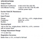
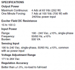
Looking at the specs on the Basler AVC they used / I'm using, I've got a budget of 252 Watts (4 Amps at 63 VDC) on the field supply circuit. I'm going by the fact that 24 volts from the Delco made 90ish volts on the MEP and your 32 volt number for full 120 VAC. I cleaned up the connections on both of the ceramic resistors the other night and just measured the one between the AVC and the Delco's field. It's right at 12 ohms. I did not measure the resistance across the field of the Delco while I had it here, but assuming this resistor is still at rated resistance, and considering the Basler's 15 ohm minimum, I'm gonna guess that the Delco's field is somewhere around 3 ohms (12+3 =15), but let's use 4 just for fudge factor. So using Ohm's law for power: if V = 32 and R = 16, then the power to drive the Delco is 64 Watts. Well within the Basler's rated 252 Watts. Or, turning the equation around, about 4 Amps at 32 volts. Again, well within the Basler's specs. If you assume that the total resistance thru the resistor and Delco field is only 15 Ohms, you still only need 68 Watts. So, I think I'm safe there. I still don't really like the 2 resistors but I guess this is just a normal requirement. It occurs to me that you really can't just dump power into what would be, effectively, a dead short or close to it, without the resistor(s).

basler field specs.PNG
 

Scoobyshep

Well-known member
1,144
1,525
113
Location
Florida
Another curveball to consider is the rated amperage output of the avr. Since thats what is actually doing the work and that is what the avr fuses are rated in.

Sent from my SM-G973U using Tapatalk
 

Scoobyshep

Well-known member
1,144
1,525
113
Location
Florida
Not following - can you explain a little?
Watt (volt*amp) so if its pushing a higher voltage and a low amperage it can push your required wattage. Now if its a lower voltage the amperage has to go up to keep the same wattage.

Sent from my SM-G973U using Tapatalk
 

Back-in-Black

Well-known member
296
277
63
Location
Louisiana
Watt (volt*amp) so if its pushing a higher voltage and a low amperage it can push your required wattage. Now if its a lower voltage the amperage has to go up to keep the same wattage.

Sent from my SM-G973U using Tapatalk
OK, I got you. It's rated for 4 amps at 63 VDC - which is just another way of saying 252 Watts. For the 64-68 Watts at 32 VDC I calculated, it's still 4 Amps of current. Just at 32V. I imagine that if the voltage increases, the R doesn't change so the current can only drop a little as the voltage increases.

If the voltage drops?. Since they don't give a max current at every voltage, I'm only guessing here but I should be OK considering it can handle 7 amps at 100 VDC (700 W) for a full minute. I would think the stuff in there is robust enough to handle it. Besides, if you do the math, and the required power (W) remains at ~68 W, the current actually is less than 3 Amps at 24 volts.

I made a math error somewhere earlier - 32 VDC on 16 Ohms is only 2 Amps.

Anyway, the way I understand it, the Wattage isn't the requirement of the field, the winding need volts / current to create the magnetic field. The power or Watts will probably vary with whatever volts it takes to get there. You can't create 68 Watts with 24 volts and 16 ohms. You get about 36 W and 1.5 amps.

Think about it. The power creation / dissipation here is mostly at the resistor in the form of heat.....
 
Last edited:

Scoobyshep

Well-known member
1,144
1,525
113
Location
Florida
R remains constant so volt and amp have to change inversely. In operation they will ramp up and down as it works. Its its base operating voltage you need to watch.

I only point it out because I had a similar situation on a 005. It looked like it would work but it kept blowing fuses.

Sent from my SM-G973U using Tapatalk
 

Back-in-Black

Well-known member
296
277
63
Location
Louisiana
Understood.

the way I understand this - and I am BY FAR NOT an EXPERT on this stuff, but anyway, the VR ramps up the voltage on the field to increase voltage generated. The more it ramps up the field voltage, the more the power dissipated at the field and current go up.

Since this thing worked for years like it was, I can only assume that the Delco is capable of putting out the required voltage and current need to drive the field of the MEP for 240V operation. Also, since the Basler ran the Delco for all those years, I gotta believe it can handle the load from the Delco.

It was probably in service for close to 10 years before it broke. The guy who gave it to me swears it only had ~200 hours on it when he bought it. The hour meter now shows 129 hours. Meter only has 4 digits so if he's right and the meter is right, he put ~ 9,870 hours on it. Don't sound right but that's what he's telling me. That's about 41 days of run time per year for 10 years. Even with all the power failures we get here and assuming it had a weekly exercise routine of 20 minutes or so, that's still a lot of days per year. Not buying it.

Anyway, I do know this thing operated like this for years. Heck, the guy who gave it to me had no clue that the Delco was driving the field of the MEP. I told him what I had discovered the other day and he wanted to argue with me at first... So I know he wasn't the one who modified it. Had to be don before he bought it in the early to mid 90's. So that just confirms that it ran like this for years - probably 10 or 12 if memory serves.
 

Back-in-Black

Well-known member
296
277
63
Location
Louisiana
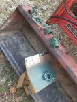
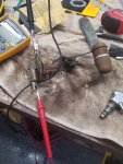
Yesterday I cleaned up radiator and thermostat fittings and painted them in the hope that it would slow down the corrosion that was going on for years. Going to make new gaskets for all of it tomorrow and put it back together to see if it still leaks. I also tested the thermostat in a pot of water on the cooktop. Works well.

Cleaned up the contact point and the resistor pad on the fuel gauge sender. Wasn't working so well when I tested it but now it works good.

20211124_145028.jpg

20211124_145000.jpg
 

Mullaney

Well-known member
Steel Soldiers Supporter
Supporting Vendor
7,719
19,767
113
Location
Charlotte NC
Yesterday I cleaned up radiator and thermostat fittings and painted them in the hope that it would slow down the corrosion that was going on for years. Going to make new gaskets for all of it tomorrow and put it back together to see if it still leaks. I also tested the thermostat in a pot of water on the cooktop. Works well.

Cleaned up the contact point and the resistor pad on the fuel gauge sender. Wasn't working so well when I tested it but now it works good.

View attachment 851595

View attachment 851596
.
Neat trick... That is a "old guy trick" that I was taught long ago.
A thermostat in a pot of water on the stove and a thermometer is the sure fire verification test!
 

Back-in-Black

Well-known member
296
277
63
Location
Louisiana
.
Neat trick... That is a "old guy trick" that I was taught long ago.
A thermostat in a pot of water on the stove and a thermometer is the sure fire verification test!

I thought everyone knew that one. Candy thermometer is the shiz!!!

As soon as everyone clears out of the kitchen, I'm gonna cook up some good ole brass temp sending unit with that same candy thermometer. Yummmm! Need to get a curve for it. Did the oil pressure sensor earlier with a regulator and a rubber tipped air nozzle from the compressor. The fuel sender was a lot easier.
 

Back-in-Black

Well-known member
296
277
63
Location
Louisiana
Some progress, some stagnation:

Got the new gaskets for the thermostat and bottom of the radiator punched out and installed. Seems to have fixed all my leaks. I say "seems" because I have not run it long enough to get it really hot so not much pressure on the system yet.

Got the temp gauge on the panel working. Barely hit 120 *F before I shut her down - don't want to wet stack it.

Plugged in the fuel sender and grounded it against a rivet on the front panel and moved the float up and down - working great.

Got the alternator (Delco) back - it had a broken / bad brush so he replaced the whole brush rack assembly.

Put it back on the set and still can't make power without using battery power. If I put 24 volts from the battery on the + output of the Delco (powers the field of the MEP) I get ~85 VAC on L1 or L3 and 175 VAC from L1 to L3. But the Delco still won't make power. When I try to put voltage on the F1 and F2 of the Delco, something inside the Delco seems to open up and then after a little while, it'll close back up. Gotta check with the repair shop and see if he just assumed that once the obviously broken brush was replaced, it'd make power.

I also checked the operation of the voltage regulator that's supposed to be powering the field of the Delco. If I disconnect the F+ and F- of the regulator from the Delco's field and put my meter across F+ and F- on the regulator while it's seeing 175 VAC on 3 & 4, I see 93 VDC across them (F+ and F-). This is pretty much what you'd expect - the regulator is seeing under-voltage (175 VAC) and it pushing 93 volts to the field trying to make 240 VAC. Since the voltage (175 VAC) is not increasing (I just have 24 volts applied the MEP's field), the regulator is going into it's 100 VDC forcing routine. This is my conclusion anyway - that the regulator is doing exactly what it's supposed to be doing.

So, pretty sure there's still a problem in the Delco. I have not been able to make any voltage with it so far, no matter what I try. As I stated above, when I apply 24 VDC to the Delco's field, something appears to open the circuit inside the Delco and some minutes after I take the 24 volts off, it eventually closes again. Going to bring the Delco back to the shop and see if he can make it put out power. I could be doing something wrong but it's a pretty simple system and I should be able to make some power by putting DC voltage on the Delco's field.

I also think I may need a new radiator cap. After I ran it several minutes and it had warmed up.... after I shut it down, I could hear pressure hissing from the cap. While it was doing this, the radiator was still cool enough for me to lay my hand on without even discomfort. I was worried that what I was hearing was compression leaking into the cooling system thru a bad head gasket. So I ran it for another ~10 minutes with the radiator cap off and watched for bubbles in the radiator. No bubbles. Will have to keep an eye on it.

basler field specs.PNG

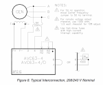
AVC schematic.PNG
 
Top
AdBlock Detected

We get it, advertisements are annoying!

Sure, ad-blocking software does a great job at blocking ads, but it also blocks useful features of our website like our supporting vendors. Their ads help keep Steel Soldiers going. Please consider disabling your ad blockers for the site. Thanks!

I've Disabled AdBlock
No Thanks