Wiring the Deuce for A/C
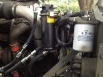
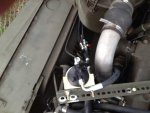
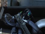
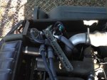
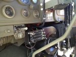
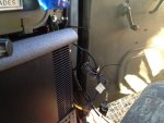
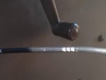
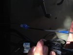
Here are some pictures of the wiring I did on the A/C for the deuce.
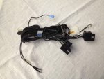
As background, I did not use one of the sub harnesses included with the system. Since the Deuce was produced way before this A/C/ system, much modification and fabrication was required. The first picture is of the unused wiring sub harness. It is the one with the 2 large female relay blocks. Mine has a soft metal tab numbered 45152-3387699. This possibly is to be used with the heater, but since I live in Central Florida I did not elect to hook it up.
I forgot to put the O-rings under the 2 pressure sensors (Switches) on the receiver/dryer. I could not get the system to hold a vacuum, and those 2 missing O-rings were the culprits. By the way, it does not matter which port you connect either sensor. They are interchangeable. Just be sure you have adequate clearance between the top of the sensors and the hood. Don’t ask how I know this.
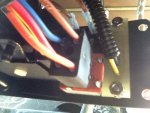
I disconnected to 3 cables from the control panel that control defrost, heat and temp. I mounted the control panel on the discharge on the evaporator. I had to drill one hole for the lower right screw hole on the panel. The 2 holes on the panel seem to be substantial enough to hold the control panel securely. It does not vibrate. I will most likely find a new spot for the panel. But for now it works fine.
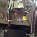
I mounted 2 on/off switches on the dash. One for the Aux Condenser Fan and one for the A/C clutch. I turn both on when I turn on the AC. Both are direct 24 V hook ups, directly to the battery with a 20 amp fuse inline from the battery to the off side of each switch. I have a 24 V junction box mounted on the passenger side above the vent, but with the evaporator installed there was little room for my size 12 hands to work in the confined space!
There is a picture of a connection from the 444 wire to the one of the 2 brown leads. The other brown lead with the blue connector goes to the on/off switch on the control panel. There is a short brown wire with a blue coming off the large plug that plugs into the back of the control panel. That brown lead with connector goes to the other side of the on/off switch on the control panel. (3 brown wires; 1 short and 1 long to the control panel on/off switch (not the 2 dash-installed switches). The other long brown wire goes to the 444 wire on the harness on the right side of the evaporator. The 444 wire had to be cut from the harness that comes through the firewall from the compressor/pressure switches, and then connects to the long brown wire with the blue end. (Are you still with me?)
Now, on the control panel harness, there is a large 5 wire plug that plugs on to the 5 blade connector. (The one short brown wire goes to the on/off switch, remember)? There is a black/yellow wire with a plug that connects to its mate. Then there are 3 wires out of the same main harness, an orange, yellow, and black. Cut the orange wire and hook it to the on side of the dash on/off switch for the A/C clutch. The black is a ground wire. Cut the yellow wire and put a wire nut on it. You will not be using this yellow wire. (To get this paragraph right, required about 4 hours of work).
Good luck! It sure is cold in here!
