• Steel Soldiers now has a few new forums, read more about it at: New Munitions Forums!

  • Microsoft MSN, Live, Hotmail, Outlook email users may not be receiving emails. We are working to resolve this issue. Please add support@steelsoldiers.com to your trusted contacts.

Alternate Alternator Selection

GeneralDisorder

Well-known member
Steel Soldiers Supporter
2,082
5,317
113
Location
Portland, OR
Keep the manual disconnect - it's very convenient for working on the truck. And keep the NATO slave receptacle. And for that matter keep the front glad hands. Everyone likes to delete this stuff but it makes jump starting and recovery a PITA for the rest of our community. It's pretty often that guys will have some sort of malfunction and need help from this forum or the Facebook groups and without those items it just make the job harder. Being able to hook up a tow-bar and have working brakes and not have to cage the parking brakes, etc is very handy. Sure you can (and might have to) call a commercial class 8 wrecker but it will cost you 4 digits and potentially 5 and they are VERY likely to break your truck. They have no idea what they are doing with our trucks. You are much better off if the community can rescue you.
 

hike

—realizing each day
Steel Soldiers Supporter
538
849
93
Location
Texas Hill Country
Yes on the 12v battery. It seems prudent to have backup in case there's a failure of the victrons while driving.

No, I removed the relay so there's no aux contacts to run the dash light. I was just thinking there could be a test connection for the switch outside by connecting 1008 to 1855. It's of no use really, just Xmas lights. It'll just be open circuited as shown now.

Only the manual disco remains. I'm on the fence about that as well for the reasons you gave, but it is possible to lock it closed. It's a nice safety device when working in the engine comp. If it fails, contacts failure, then I'd have a possible issue but that seems low probability. Idk
View attachment 918072
We dropped the 12v backfeed, though will have 2-banks of 2-31's separated by a battery combiner which will allow the second bank to start assist, if need.

We removed the LBCD and battery relay disconnects as you did, though brought the 24v alternator to the battery side of the manual disconnect. Batteries and alternator always connected—
 

MatthewWBailey

2025 !!
Steel Soldiers Supporter
867
1,572
93
Location
Mesa Colorado
Keep the manual disconnect - it's very convenient for working on the truck. And keep the NATO slave receptacle. And for that matter keep the front glad hands. Everyone likes to delete this stuff but it makes jump starting and recovery a PITA for the rest of our community. It's pretty often that guys will have some sort of malfunction and need help from this forum or the Facebook groups and without those items it just make the job harder. Being able to hook up a tow-bar and have working brakes and not have to cage the parking brakes, etc is very handy. Sure you can (and might have to) call a commercial class 8 wrecker but it will cost you 4 digits and potentially 5 and they are VERY likely to break your truck. They have no idea what they are doing with our trucks. You are much better off if the community can rescue you.
Yeah I'm not deleting anything that makes my life easier. I've used that front gladhand a few dozen times already just to release the brakes. Pretty convenient! Plus I have the gladhand adapter and hose for airing up tires manually (if needed) since my CTIS is out of order. I have 2 sets of nato slave receptacle hookups, one big honking set for nato-to-nato connection, 20' 4/0 cable that was a used find on eBay, if I ever need a jump from another lmtv. The other is just a nato plug with 1' long cable and bare battery connections I use for jumping with my jump-and-carry unit, or for external charging on demand.
 

Attachments

MatthewWBailey

2025 !!
Steel Soldiers Supporter
867
1,572
93
Location
Mesa Colorado
We dropped the 12v backfeed, though will have 2-banks of 2-31's separated by a battery combiner which will allow the second bank to start assist, if need.

We removed the LBCD and battery relay disconnects as you did, though brought the 24v alternator to the battery side of the manual disconnect. Batteries and alternator always connected—
Yes I like that arrangement too. The separate 12v battery isn't really necessary with 2 victrons powering up the 12v side. I'm always thinking about what happens when stuff breaks, while driving. The wires are already there and it's no extra cost to leave the battery there.
 

Ronmar

Well-known member
3,896
7,563
113
Location
Port angeles wa
the manual disconnect is handy for maintenance. i havn't added one, but I will when I get my final configuration sorted out. As for backup, that is what the house battery cross tie will be for:)
 

MatthewWBailey

2025 !!
Steel Soldiers Supporter
867
1,572
93
Location
Mesa Colorado
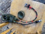
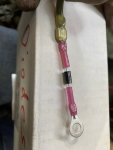
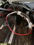
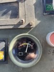
I got tired of typing my dreams and just started it up. The "charging system" light works as expected. Tested it firsts and it's good. See pics of diode assembly. I appreciate you guys making this happen🫡🇺🇸

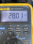
Alt produced 99amps with the AIH on and batteries a little drained(only 2). Then with AIH off it went to 20A and 28.02v. Not much movement in voltage. Batts were tracking 0.1v less than at the alt terminal.

new serpentine was fine but was close to short. My old belt was 80" and I mistakenly used the parts spreadsheet to measure from and that says 78.25". The one on there now is 68-5/8". I've got 1/4" of gap on the top tensioner limit. Close.

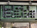
now onto the PDP board. Mine doesn't look like the manual but I was going to use the radio CB20 as a power feed for the victrons.


Attachments

MatthewWBailey

2025 !!
Steel Soldiers Supporter
867
1,572
93
Location
Mesa Colorado
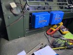
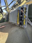
Finally wired up my 12v victrons. I already had 2 of these 24/12-20 units with Bluetooth, for another project. I couldn't really find a good breaker to hook them to so I just added a 30a fuse off of X3 and paralleled the 2 outputs onto X2. The Bluetooth setup allows for monitoring and changing settings.

set the low input cutout for both to 22v and the reset to 27.5v. That way, these won't turn on until the starter's done and then AIH finishes, then a delay for voltage to return to 28. Should act like a reactive timer function.

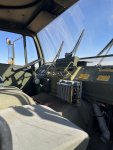
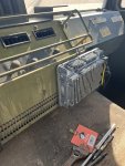
There's no room for these inside so they're attached to the center console. I'm making a stainless cover for the center console foot area to house these and some other things later so these will be open for now. Helps with Bluetooth anyway.

With everything 12v I could turn on at once, I was only pulling 14.8 amps. So 2 units is definitely overkill.
 

Attachments

MatthewWBailey

2025 !!
Steel Soldiers Supporter
867
1,572
93
Location
Mesa Colorado
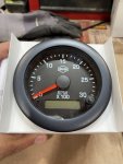
Update. I'm posting here on the alt driven tach signal bc I've no clue where else to post. There's a lot of various tach threads. I hooked up this IssPro tach, using pulses per rev. Works except the PPR numbers didn't calibrate at all. Assuming my idle/fast idle is 700/1350, something is off. I measure the pulleys at 3" and 7.5" which is 2.5 ratio. Alt manual says 10pulses per rev. That's 25 ppr on the guage setting. At that setting, idle reads at 400 fast idle 800. So I lowered to 16ppr. Now I'm at 650/1250. I assume those are supposed to be 700/1350 per ECM program? So, Either the alt is only 6 pulses per rev or my tape measure is metric. I guess I need to dig out my strobe GDI 🤬.D06FD8C8-5E1C-4131-B978-AB92DFFDFE27.jpeg
 

reb87

Member
602
16
18
Location
Nebraska
I really appreciate the info in this thread. I picked up this 24v alternator https://www.amazon.com/gp/aw/d/B0BFT4416K?psc=1&ref=ppx_pop_mob_b_asin_title
Used one of the 100 amp bussmann equalizers
P/N 21100E00
And dumped the dual voltage junk on my 2004 m1088a1 I just drilled out the top mounting bracket hole and made a bottom arm to hook to the new alternator. So far it’s working great.
 

Attachments

MatthewWBailey

2025 !!
Steel Soldiers Supporter
867
1,572
93
Location
Mesa Colorado
I really appreciate the info in this thread. I picked up this 24v alternator https://www.amazon.com/gp/aw/d/B0BFT4416K?psc=1&ref=ppx_pop_mob_b_asin_title
Used one of the 100 amp bussmann equalizers
P/N 21100E00
And dumped the dual voltage junk on my 2004 m1088a1 I just drilled out the top mounting bracket hole and made a bottom arm to hook to the new alternator. So far it’s working great.
So that is the exact same 28SI Delco alternator as mine, only yours is J180 mount. Your number below in red. Nice it's only $130!!IMG_5880.jpeg
 

MatthewWBailey

2025 !!
Steel Soldiers Supporter
867
1,572
93
Location
Mesa Colorado
Update. I'm posting here on the alt driven tach signal bc I've no clue where else to post. There's a lot of various tach threads. I hooked up this IssPro tach, using pulses per rev. Works except the PPR numbers didn't calibrate at all. Assuming my idle/fast idle is 700/1350, something is off. I measure the pulleys at 3" and 7.5" which is 2.5 ratio. Alt manual says 10pulses per rev. That's 25 ppr on the guage setting. At that setting, idle reads at 400 fast idle 800. So I lowered to 16ppr. Now I'm at 650/1250. I assume those are supposed to be 700/1350 per ECM program? So, Either the alt is only 6 pulses per rev or my tape measure is metric. I guess I need to dig out my strobe GDI 🤬.View attachment 922116
Final update on this. I got this unit recalibrated using the strobe. I'm dead on 700 at idle and 1350 at fast idle, matching the strobe. The tach settings had to be massaged to 14ppr. Eventually I'll add that Blue Fire thing to read all that ECM info but this works great for now as a tach off the Alt "R" terminal.
 

MatthewWBailey

2025 !!
Steel Soldiers Supporter
867
1,572
93
Location
Mesa Colorado
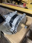
More possibilities emerge! After researching the Denso alts, I was unable to verify pad mount dimensions. Typical since auto parts are almost exclusively about make and model of vehicle. ( I put the Delco on there in March).

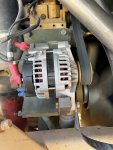
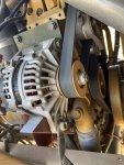
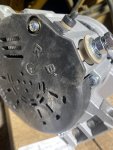
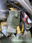
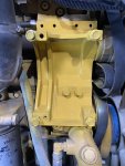
I had identified a cat part number for an Alt that fits a 3126 as 272-1889. That led me to a Denso unit with interchange # of 101210-9010. But no one advertises the pad dimensions fully & The pad on a 3126 A1 truck is 4.25" x 7.5" for the inner set of holes. (7.45") I took a chance on the Delco Remy Alt and it fit perfectly. So, why not try again? I need a spare anyway. So, The 101210-9010 alt I found is a 150Amp, 24v and $437 on eBay free shipping. Received it today and it fits👍. Holes are 4.25 x 7.5 just like the Delco.

Definite upgrade from 110 to 150 but still padmount!

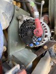
now this Denso only has B+ and R terminals whereas the smaller Delco has S, I, R and B+. Minor impact since R can be used to drive the "charge system" light if desired.

this particular unit is a replacement on a slew of Cat machines including a C7.1 engine, which is why I took the chance.

Anyway, another option for padmount if desired🥳

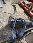
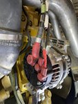
IMG_6009.jpegIMG_6008.jpegIMG_6013.pngIMG_6014.pngIMG_6012.png
 

MatthewWBailey

2025 !!
Steel Soldiers Supporter
867
1,572
93
Location
Mesa Colorado
It's been a while so take with a grain of salt, but I thought there were two standards for pad mounts and we have the mounting holes for both.
Yes, There's an extra set of holes on the left side that are 5.25" I believe, that's what the J180 plate attaches too. However, I've found no pad mounts, SO FAR, that fit to that set of holes.
 
Top
AdBlock Detected

We get it, advertisements are annoying!

Sure, ad-blocking software does a great job at blocking ads, but it also blocks useful features of our website like our supporting vendors. Their ads help keep Steel Soldiers going. Please consider disabling your ad blockers for the site. Thanks!

I've Disabled AdBlock
No Thanks