Hey, y'all. I'm helping a friend work on Gen2 on his '86 m1008. We used the schematics on here and I wired it accordingly. We replaced the bulb in the dash for the Gen2 light to complete the circuit; however, anytime I wire it to the correct spec I short the batteries. We have to wire it funky to keep it from shorting, but we still believe that to be the main problem for it not charging the 1 battery. Any suggestions before I decide it necessary to do a complete pull of each wire?
-
Steel Soldiers now has a few new forums, read more about it at: New Munitions Forums!
Alternator Shorting battery
- Thread starter Shall1225
- Start date

More options
Who Replied?- 2,104
- 669
- 113
- Location
- Orlando, FL
Is alternator #2 isolated ground?
It has an isolated ground. Post. From the schematic and tech manual it looks like both the red/white wire and the black ground wire connect to it but I might be wrong. Either way they aren't connected there right now.Is alternator #2 isolated ground?
MarcusOReallyus
Well-known member
- 4,524
- 819
- 113
- Location
- Virginia
Don't do that!We have to wire it funky to keep it from shorting,
Any suggestions before I decide it necessary to do a complete pull of each wire?
Don't do that, either.
Can you explain a bit what you mean? How did you verify isolated ground?It has an isolated ground. Post.
From the schematic and tech manual for the truck it looks like the iso ground post needed to be on the alternator so we purchased an alternator with one on it. But it was wired incorrectly when he bought it with the old alternator and we haven't been able to change how it is because it'll short if it's not set up correctly.Don't do that!
Don't do that, either.
Can you explain a bit what you mean? How did you verify isolated ground?
Attachments
-
36 KB Views: 16
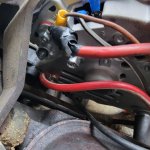
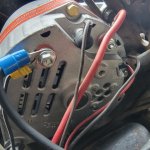
This is how it was wired on the old alternator. Looks like red/white wire is on the positive, 2nd post is jumped from that. The solid red and the orange diag wire were crimped together. That's how he bought it. Without the solid red and diag touching, it shorts the battery. Now we have it set up pretty much the same except I don't have the 2nd post jumped anymore. Having it run directly from the positive terminal board like it's supposed to. Try configuring the wires multiple ways including multiple times by the tech manual but everything shorts the battery besides this set up.
- 2,104
- 669
- 113
- Location
- Orlando, FL
The new alternator has the isolated ground on it but even when the red/white is connected to it, it shorts. That's why even with the new alternator it's wired the same as this pictured old oneThe alternator in the pictures is not isolated ground.
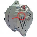
The circle in the picture is the ground on an isolated ground alternator.
View attachment 858654
- 2,104
- 669
- 113
- Location
- Orlando, FL
Why don't you take a picture of what you have now so maybe we can help you?
Barrman
Well-known member
- 5,351
- 1,998
- 113
- Location
- Giddings, Texas
Can you put an Ohm meter on the isolated ground post with one lead and on the case of the alternator with the other and not have continuity? Verify it really is an isolated ground alternator first.
There is no continuity to the post. It is isolated. This is also how the current alternator is set up. Red/ white wire to positive terminal. Small red wire to 2nd port brown/ white wire to 1st port, and then large red wire and orange 20A fuse link wire are pinned together, completely off the alternatorCan you put an Ohm meter on the isolated ground post with one lead and on the case of the alternator with the other and not have continuity? Verify it really is an isolated ground alternator first.
Attachments
-
137.5 KB Views: 30
MarcusOReallyus
Well-known member
- 4,524
- 819
- 113
- Location
- Virginia
Time to start fresh. That's not stock, and there's no telling what kind of mess someone made out of it.
- 2,104
- 669
- 113
- Location
- Orlando, FL
If this is an isolated ground alternator and there is no connection to the isolated ground terminal (I don't see one in the picture), the alternator will not work. If you were to connect the positive post from the front battery directly to this terminal and it's isolated from ground, it cannot short the battery because it's isolated.There is no continuity to the post. It is isolated. This is also how the current alternator is set up. Red/ white wire to positive terminal. Small red wire to 2nd port brown/ white wire to 1st port, and then large red wire and orange 20A fuse link wire are pinned together, completely off the alternator
Time to get your meter and check where the wires connected to the alternator go. The one on the positive terminal should go to the rear battery positive post. One of the others should go to the rear battery negative post.
In a nut shell, the front battery negative post goes to the vehicle ground/chassis etc. The front battery positive post connects to the rear battery negative post. The vehicle 12 volt supply is also pulled from this junction. The #2 alternator isolated ground connects to the rear battery negative post. Since the rear battery negative post is connected to the front battery positive post, it cannot connect to ground. Alternator #2 positive terminal connects to the rear battery positive post which is connected to the vehicle 24 volt bus.
The isolated ground is circled below. I will reconnect the ground wire that is connected to the frame to see if it makes any difference as it wasn't connected to the old one.If this is an isolated ground alternator and there is no connection to the isolated ground terminal (I don't see one in the picture), the alternator will not work. If you were to connect the positive post from the front battery directly to this terminal and it's isolated from ground, it cannot short the battery because it's isolated.
Time to get your meter and check where the wires connected to the alternator go. The one on the positive terminal should go to the rear battery positive post. One of the others should go to the rear battery negative post.
In a nut shell, the front battery negative post goes to the vehicle ground/chassis etc. The front battery positive post connects to the rear battery negative post. The vehicle 12 volt supply is also pulled from this junction. The #2 alternator isolated ground connects to the rear battery negative post. Since the rear battery negative post is connected to the front battery positive post, it cannot connect to ground. Alternator #2 positive terminal connects to the rear battery positive post which is connected to the vehicle 24 volt bus.
Attachments
-
66.3 KB Views: 30
MarcusOReallyus
Well-known member
- 4,524
- 819
- 113
- Location
- Virginia
Have you personally used a meter to verify that there is no continuity between the ground post and the case?The isolated ground is circled below.
I have. I told my friend that owns it the next best step is to remove all the wires off of the terminal boards and run continuity through each wire to ensure it is the correct wire connected. Also on the diagram below, where exactly is this component in the bay?
Attachments
-
22.2 KB Views: 22
- 2,104
- 669
- 113
- Location
- Orlando, FL
I think I may see your problem. The ground terminal on alternator #2 does not connect to the chassis ground, only to the negative battery post of the rear battery. Since the positive post on the front battery and the negative post on the rear battery are connected (the front and rear batteries are wired in series to get 24 volts), connecting the negative terminal on alternator #2 to chassis ground will short the front battery.The isolated ground is circled below. I will reconnect the ground wire that is connected to the frame to see if it makes any difference as it wasn't connected to the old one.
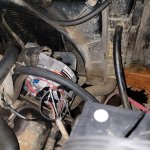
Here are both alternators wired. Still shorting.
Attachments
-
120.1 KB Views: 27
-
125.3 KB Views: 24
- 2,104
- 669
- 113
- Location
- Orlando, FL
Do this first. Take the wire(s) off alternator #2's negative terminal and tape them up. Run a test wire from alternator #2's negative terminal to the negative post on the rear battery. Verify the large wire connected to the positive terminal on alternator #2 goes to the rear battery positive post. Once you have the wires connected to the positive and negative terminals on alternator #2, you should see 12 volts across them.
Start the truck and see if it charges. Ignore the idiot lights on the dash and check the voltage on each battery. If it doesn't charge, do this.
Since the wiring has been changed, you will need to draw a diagram of where each wire goes and post it. It's impossible to tell from a picture of one end of the wire when the colors are different. Don't worry about the regulator wires for now. Take the big wad of electrical tape off the wire on alternator #2, you can't tell what is connected there. It looks like there are two wires on the negative terminal on alternator #2, are there? My truck only has one, where do they go? Take a picture of the batteries.
- 112,579members
- 166,187threads
- 2,340,655posts
- 906online users


