• Steel Soldiers now has a few new forums, read more about it at: New Munitions Forums!

  • Microsoft MSN, Live, Hotmail, Outlook email users may not be receiving emails. We are working to resolve this issue. Please add support@steelsoldiers.com to your trusted contacts.

AMMPS Generator Series Remote Data

FarmingSmallKubota

Well-known member
Steel Soldiers Supporter
466
1,103
93
Location
Wapakoneta, Ohio
As i try to read through what ever this is That I have no idea about. the movie Billy Madison keeps popping in my head. I wish you good luck with what ever you are trying to accomplish and with that a quote.
“Mr. Madison, what you’ve just said is one of the most insanely idiotic things I have ever heard. At no point in your rambling, incoherent response were you even close to anything that could be considered a rational thought. Everyone in this room is now dumber for having listened to it. I award you no points, and may God have mercy on your soul.” — Principal
 

kloppk

Well-known member
Steel Soldiers Supporter
2,129
3,496
113
Location
Pepperell, Massachusetts
Ya something is weird in the code on initial connection, it seems it starts comms on the ui thread and then spawns a new thread just for comms and uses that from then forward, but only after it has requested data the first time...not sure if an oversight or intended but that may describe why it is doing weird stuff on initial data request.
Ah, glad you spotted something odd in the code that may explain what I'm seeing. Easy enough to deal with. Request data, ignore the response and request again to get good data.
I can work on a timeline of the back and forth between the PC an DCS for each PC request from initial baud rate negotiation thru good parameter data from the DCS. That should help with creating your DCS simulator. Putting my digital O'scope to good use!

My pins arrived today to add to the P3 connector to sniff for CAN data. More work ahead in that area.
 
Last edited:

kloppk

Well-known member
Steel Soldiers Supporter
2,129
3,496
113
Location
Pepperell, Massachusetts
I tweeked my RS-232 sniffer code and there are no longer checksum errors.
I also now see what appears as the first requests for real data may be additional handshaking since it's way more than 44 requests.
More digging...
 
Last edited:

Icesythe7

Active member
147
223
43
Location
Indiana, USA
I tweeked my RS-232 sniffer code and it now looks there are no longer checksum errors.
I also now see what appears as the first requests for real data may be additional handshaking since it's way more than 44 requests.
More digging...
could be, like I said I can't really make heads or tails of it in the code I just know it runs some coms on the main thread and then spawns a new thread and switches to that after some communication has taken place
 

ilajnfae

New member
22
0
1
Location
Kentucky, USA
What I have so far in an Excel file today with set running and loads on L1 & L2, RS-232 data captured and decoded.
Serial Data Baud Rate between DCS & PC 115,200 over 100' of CAT5 cable
View attachment 911795


Remote Screen at almost the same time for comparison
View attachment 911792
I'll be sending updates via PM's to Icesythe7 & R1ckyb0nd so that this thread doesn't become huge 😳
When reviewing my capture, it seems the remote monitoring software and the generator are trying to negotiate the fastest baud rate possible. It send a bad rate request, gets and ack. Then sends char and other data stream settings. Then does this several times with faster baud rates. Then it starts sending requests for data
Good afternoon:

New user here, I've got a DCS I'm attempting to checkout / repair. Am I correct in assuming that you are capturing this serial data via pins 7 and 8 on the 'Remote' connector feeding a 232/485 serial port ? Any information would be appreciated!
 

kloppk

Well-known member
Steel Soldiers Supporter
2,129
3,496
113
Location
Pepperell, Massachusetts
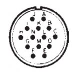
The remote port pins are NOT labeled with numbers. They are labeled with the letters A thru N.
It's a RS-485 port.

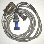
The cable I'm using. 6150-01-608-2635 PN 04-21227 with the blue RS-485 to RS-232 adapter on it
Remote Monitor Cable.jpg

Wiring diagram for the cable above. For Remote Monitoring the RS-485 is on "P2 Main" DB9 connector below.
Remote Cable 6150-01-608-2635   PN 04-21227.jpg


This is the pinout of the connector that mates to the DCS's Remote Port. Its PN is MS3106E20-27P
Remote Cable Pins.jpg
 

ilajnfae

New member
22
0
1
Location
Kentucky, USA
The remote port pins are NOT labeled with numbers. They are labeled with the letters A thru N.
It's a RS-485 port.

The cable I'm using. 6150-01-608-2635 PN 04-21227 with the blue RS-485 to RS-232 adapter on it


Wiring diagram for the cable above. For Remote Monitoring the RS-485 is on "P2 Main" DB9 connector below.


This is the pinout of the connector that mates to the DCS's Remote Port. Its PN is MS3106E20-27P
Fair enough, much appreciated, I'd built a DB-25 breakout for the connector and mis-interpreted the signals I was seeing. Interestingly, though I've not found documentation for it in the TM I'm working from, it also appears that pin E is the remote wake command (DCS turns on when E grounded) and pin J is the remote E-stop. Thanks again for the rapid reply!
 

ilajnfae

New member
22
0
1
Location
Kentucky, USA
You are correct. The current available TM does not have any info on the wiring of the Remote port.
Thanks again for the assist. I know you, Icesythe7 & R1ckyb0nd moved out of this thread to keep it from growing uncomfortably large, but how is the 1939 effort moving along? tackling the CAN bus interface will be my next challenge :)
 

R1ckyb0nd

Member
47
11
8
Location
Ct
Thanks again for the assist. I know you, Icesythe7 & R1ckyb0nd moved out of this thread to keep it from growing uncomfortably large, but how is the 1939 effort moving along? tackling the CAN bus interface will be my next challenge :)
I am wiring up some Can bus terminators to mu ESP-32s and to a Jetson nano to try and connect to the J1939 Bus. I tried connecting to the Diagnostic port near the engine and I did not get anything, but that could have been a bad USB-Canbus converter from WaveShare..
I am going to go get the DCU from the generator I have to start bench testing some things. I think if I add 24V to the ABC+ def- pins of P2 it will turn on.. Then I should get something, even blank CAN messages on P3 pins K and L

I truely believe the 1939 is the way to go.
 
Last edited:

ilajnfae

New member
22
0
1
Location
Kentucky, USA
I am wiring up some Can bus terminators to mu ESP-32s and to a Jetson nano to try and connect to the J1939 Bus. I tried connecting to the Diagnostic port near the engine and I did not get anything, but that could have been a bad USB-Canbus converter from WaveShare..
I am going to go get the DCU from the generator I have to start bench testing some things. I think if I add 24V to the ABC+ DEF- pins of P2 it will turn on.. Then I should get something, even blank CAN messages on P3 pins K and L

I truely believe the 1939 is the way to go.
Can confirm that ABC at 24 to 28+ and RTN at DEF will power up the DCS and that depending on selection made by the Engine ID switches it will live up the 1939 at K and L. it shouts into the abyss for a timeout period and then declares 'CAN bus degraded' . I ONLY have the DCS, so lmk if you want to fire it up in isolation and I can potentially help making the DCS happy with any missing external signals (except CAN) :) or engine IDs that will work. Nice chatting with you.
 

R1ckyb0nd

Member
47
11
8
Location
Ct
Can confirm that ABC at 24 to 28+ and RTN at DEF will power up the DCS and that depending on selection made by the Engine ID switches it will live up the 1939 at K and L. it shouts into the abyss for a timeout period and then declares 'CAN bus degraded' . I ONLY have the DCS, so lmk if you want to fire it up in isolation and I can potentially help making the DCS happy with any missing external signals (except CAN) :) or engine IDs that will work. Nice chatting with you.
Are you able to capture the traffic before it times out?
 

ilajnfae

New member
22
0
1
Location
Kentucky, USA
I have a 1939 transceiver IC that I pulled from a different system, so yes, I can visualize / decode the stream on an oscilloscope, and I have a CAN/USB adapter arriving hopefully today.
 

R1ckyb0nd

Member
47
11
8
Location
Ct
Can confirm that ABC at 24 to 28+ and RTN at DEF will power up the DCS and that depending on selection made by the Engine ID switches it will live up the 1939 at K and L. it shouts into the abyss for a timeout period and then declares 'CAN bus degraded' . I ONLY have the DCS, so lmk if you want to fire it up in isolation and I can potentially help making the DCS happy with any missing external signals (except CAN) :) or engine IDs that will work. Nice chatting with you.
What amps is your 24v power supply?
 

ilajnfae

New member
22
0
1
Location
Kentucky, USA
Good morning, and apologies for the delay. As I mentioned, I only have the DCS itself and am therefore simulating the current draw of the contactor, fan relays, etc. The electronics/display of the DCS itself, however, have never drawn more than 0.75A @ 28 VDC, so based on my experience you should easily be able to fire it up with a 1 amp supply. For my most recent purposes, I've also been applying a GND at J3-LL, which forces the DCS to expect a 30 kW, 120/208, 60 Hz environment and guarantees CAN activity
 
Last edited:

R1ckyb0nd

Member
47
11
8
Location
Ct
Are you able to capture the traffic before it times out?
Can confirm that ABC at 24 to 28+ and RTN at DEF will power up the DCS and that depending on selection made by the Engine ID switches it will live up the 1939 at K and L. it shouts into the abyss for a timeout period and then declares 'CAN bus degraded' . I ONLY have the DCS, so lmk if you want to fire it up in isolation and I can potentially help making the DCS happy with any missing external signals (except CAN) :) or engine IDs that will work. Nice chatting with you.
I just tried hooking up Pos 20V to ABC and - to def and for a few seconds the green background lights lite up, but then they went away, nothing ever on the screen.
DEF on the diagram are more B+ connections. are you sure that is what you are connecting to?
 

Attachments

ilajnfae

New member
22
0
1
Location
Kentucky, USA
I just tried hooking up Pos 20V to ABC and - to def and for a few seconds the green background lights lite up, but then they went away, nothing ever on the screen.
DEF on the diagram are more B+ connections. are you sure that is what you are connecting to?
Apologies, apparently it auto-capitalized. It should be little d,e,f :)
 

R1ckyb0nd

Member
47
11
8
Location
Ct
With 20v+ on ABC and ‐ on def, I am only getting the panel lights. Maybe my power supply is not strong enough.
 
Top
AdBlock Detected

We get it, advertisements are annoying!

Sure, ad-blocking software does a great job at blocking ads, but it also blocks useful features of our website like our supporting vendors. Their ads help keep Steel Soldiers going. Please consider disabling your ad blockers for the site. Thanks!

I've Disabled AdBlock
No Thanks