• Steel Soldiers now has a few new forums, read more about it at: New Munitions Forums!

  • Microsoft MSN, Live, Hotmail, Outlook email users may not be receiving emails. We are working to resolve this issue. Please add support@steelsoldiers.com to your trusted contacts.

Another CTIS troubleshooting thread. Power related

Primussucks

Member
Steel Soldiers Supporter
56
54
18
Location
Dallas'ish, TX, USA
Been busy getting a bunch of things in order (brakes, eco hubs, etc.) and finally getting around to troubleshooting CTIS.
CTIS has not worked since i got the truck. No lights on the ECU.

I followed the ETM (A1R truck) through the troubleshooting steps.

Before I go moving wires around...
I tested P110-H for power. Nothing.
I tested continuity between P110-H and P111-E. Tests good
P110-H is supposed to get 24v power from P111-E. I got nothing.

Tested for 24v power on J111.
Power should also be on E.. but it is not.. It is on G (J111-G).
J111-G->P111-G->P110-S (This is supposed to be power on P110-H)
Connecting everything back together.. Indeed, I'm getting 24v power on P110-S instead of H.
ds
I assume anything is possible, but is it common to have a mixed up wire in the harness (J111)?

I'm new to electrical troubleshooting.. but know some basics...
 

Ronmar

Well-known member
3,931
7,620
113
Location
Port angeles wa
The power on 111 G is used by the controller for the CTIS overspeed indication in the idiot panel. It comes from K52 and will go away if you select blackout lighting on your main light switch. keeps CTIS from violating light discipline:)

You need to troubleshoot power from 111 E back to CB40 which is its source...
 

Primussucks

Member
Steel Soldiers Supporter
56
54
18
Location
Dallas'ish, TX, USA
I'm sure it's somewhere in the schematics...
but got through another troubleshooting step.
one of the steps says to check resistance on j112-b and j112-d

resistance was not in range (30-80 ohms).

The reason I checked here is... I've seen the lights come on on the unit twice. once after i cleaned and unclogged all the all the ctis air lines during the hub service. my truck didn't come with wheel valves, and the port on the hubs were left open. they were full of grime. And another time after that. just come on briefly.. blink for a short period.. and then all lights go off and don't come back on.

ETM troubleshooting says if resistance is bad across those pins, replace the whole manifold...is that right? or just the transducer?
 

Ronmar

Well-known member
3,931
7,620
113
Location
Port angeles wa
112 b to d is just across the control solenoid coil in the PCU manifold, but that wouldn't effect the unit not powering up, and certainly would not effect power available at pin 111-E... If you don't have a CTIS switch in your truck, the power should go right from CB40 J111. If it was supposed to have a switch and that switch was removed, that could be your issue, so the power may run from CB40 to where that switch is supposed to be located. Not strictly familiar with the A1 dash, so someone else can probably tell you exactly where that switch is supposed to be located, and you will be looking for that wire 1911 there...

there should be 2 wires off of CB40, one goes to K52 and on to J111G for the overspeed light and the other either goes to that CTIS switch, or directly to J111E...
 

Primussucks

Member
Steel Soldiers Supporter
56
54
18
Location
Dallas'ish, TX, USA
made a bit more progress.
tried chasing j111-e towards CB40... didn't make it.
after i cleared a bunch of room in the bundle. I was able to find j111-e traverses the cab bundle.
looks like CB40 also traverses the cab.
next stop.. open the dash and see whats behind door#2.

k52? i couldn't find that.

trying to look at the schematic on the ETM on a ancient toughbook is unreadable. any tricks?
 

Ronmar

Well-known member
3,931
7,620
113
Location
Port angeles wa
Oh, they changed that function from K52 on the A0 to K29 in PDM#1 on the A1R(sheet 20 and 21 in the diagram). For the most part the basic wiring is VERY similar from A0-A1-A1R with only a few exceptions, this is one of them:)

I suspect somewhere you will find P913 under the pax dash, forward of the heater or in under the park and trailer air controls, and it will probably be sporting a loose opt jumper from pin 6 to 12 (seen above the ctis switch in the diagram you posted earlier). I say probably loose because you have seen the controller lights on briefly and that required a circuit that at some point briefly fed J111 pin E with useable power…

yea the electronic manuals can be problematic …
 

Primussucks

Member
Steel Soldiers Supporter
56
54
18
Location
Dallas'ish, TX, USA
@Ronmar Amazing!!!
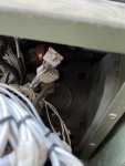
fresh brain... went out this morning.. pulled the dash open and found j913. it was as you suspected... no jumper at all. my only guess is that it bounced its way out and is somewhere behind the dash?

IMG_4116.jpeg
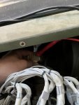
I toned everything, leg by leg back to and through the cb40, back to the j111 all the way back to p110. Continuity all the way...
IMG_4117.jpeg

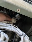
and finally jammed a jumper wire between 6 and 12...
IMG_4118.jpeg

and SUCCESS!!!

I'm grateful for this community... and that I was able to successfully, methodically, troubleshoot the circuit.

q:
for the jumper.. what type of pins do i crimp on there? I'm going to secure it similar to the other jumpered plugs back there, just wasn't sure on the right pin type.
 

Ronmar

Well-known member
3,931
7,620
113
Location
Port angeles wa
On the back side of that connector, is there one or 2 wires crimped into the back of the pin 6 and 12 locations?. It could have been that the jumper was hardwired on the back side of the Plug and loops out into the harness and back. so production only has to make one type harness, then the assembly folks would simply cut the option jumper on trucks with the aux panel and CTIS sw installed? If it is in the wire bundle, you can simply splice it back together with a butt splice…

Not sure about the pins for those, have never researched them. I suspect they are similar to Molex. Is that the male or female end? If it is the female, a similar sized wire gauge, stripped and tinned/soldered should work fine. Once tinned you can bend slightly to control tension when inserted then tape over the end of the connector to secure it.
 
Top
AdBlock Detected

We get it, advertisements are annoying!

Sure, ad-blocking software does a great job at blocking ads, but it also blocks useful features of our website like our supporting vendors. Their ads help keep Steel Soldiers going. Please consider disabling your ad blockers for the site. Thanks!

I've Disabled AdBlock
No Thanks