While Mike [
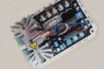
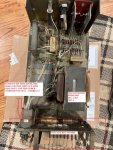
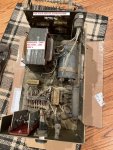
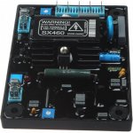
@catienla ] was waiting for his A11 to be repaired, we experimented with the ADVR 054 he had bought.
{Edit} Just to make sure: Remove A11 before doing anything else by completely disconnecting J9 and J13!
Also disconnect the two wires from J9 to TB 16! This way the new system is completely separated from the old system!
Here are the results:
After a cumbersome deciphering of several ADVR 054 manuals, which I found on various, US, Taiwanese and Chinese Websites and which all had been translated fairly poorly from Chinese into English, the following facts became clear:
1. The High Voltage supply side [ A, BB, C ] uses A as internal Ground to F-
2. The Minimum Resistance this ( as well as many other ) ADVR needs to connect to for a Exciter Coil Resistance is: 15 Ohm
3. The Maximum Resistance for exciter Coil is: 100 Ohm
4. The minimal residual Voltage for self excitation this ADVR needs on A and C in our wiring connection is: 5 VAC with 25 Hz Minimum
5. Some ADVR 054 ( and other type ADVR ) Manuals suggest the following if the minimum for # 4 is not met:
Disconnect your exciter coil from ADVR and connect to a 7 VDC to 12 VDC Battery {edit} for app 3 to 5 seconds to built up residual magnetism.
They tell you do this while Genset is not running.
Then connect exciter Coil back to F+ and F- on ADVR
( observe correct polarization, F1 lead {edit} should have been connected to + Terminal of 7 VDC to 12 VDC Battery )
Start Generator, observe Voltage and Frequency Gauge on Genset Panel.
Follow the adjustment procedures in the ADVR manual for Stability and Voltage
This assumes the following:
You have installed the correct Rheostat for manual voltage adjustment or
left the jumper on the VR VR terminals
You have connected A BB C correctly to your Generator according to your Voltage Setup!
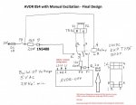
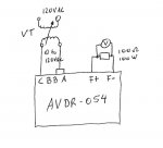
We recommend therefor the following Wire Diagram for a Manual Excitation System (Genset set to 208/230 3P):
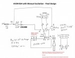
The 12 Ohm / 500 W resistor will prevent overload to ADVR for coil resistances below 15 Ohm
The 2pcs 50 Ohm / 50 Watt in series or 1pcs 100 Ohm / 100 W Resistor serves as minimum load and provides with the push button and the Relay the ability to field excite the Genset after the Genset has started.
The ADVR 054 and the SX460 will drive the F+ / F- terminals up to the full AC Input Voltage without a Load Resistor
( hence minimum resistance required )! In our case here, the Maximum Resistance becomes the Minimum Resistance when F1 and F2 are disconnected by the Relay for excitation from ADVR!
This will assure a successful excitation upon every start, even if the Genset sat for a prolonged period of time and has lost any residual magnetism as a result of it.
The ADVR 054 has a 5 Amp Fuse built in for protection.
If you use a ADVR like the SX 460 then you want to add two fuses:
1pcs 5Amp Fuse for one leg of the High Voltage Supply and 1pcs Fuse 10 Amp on the F+ leg before the 12 Ohm / 500 W resistor.
I have edited all previous Wiring Diagrams to redirect to this Post #11 in this Thread
If anyone is interested to adapt this system here, to work with the S9 switch for automatic excitation, then please contact me via PM, as this requires further testing and validation.
Mike has currently implemented the above Wiring Diagram and had his House in WV running on this setup for several hours until he ran out of fuel in his Genset. Mike has not done any other testing then this one test as he and his wife are out sick at the moment.
Get well soon!
Peter
