• Steel Soldiers now has a few new forums, read more about it at: New Munitions Forums!

  • Microsoft MSN, Live, Hotmail, Outlook email users may not be receiving emails. We are working to resolve this issue. Please add support@steelsoldiers.com to your trusted contacts.

Battery spark after new Alternator

LogdeC66

New member
6
0
1
Location
Canton, Georgia
Hey guys, I let my M1009 set for around 5 years and have taken to a shop to fix a wiring? Issue and get it running - and sold.
Before i set it to the side, I replaced the alternators, but once the new batteries were hooked up, I had sparks fly once the Negative cable touched.
It’s been so damned long since I replaced the alternators, I seem to recall that once needs to be grounded internally?
The mechanics have both my CUCV (M1028) to look at for wiring comparison but have been stumped for over a month.
How can I test the alternators to see if they are correct - if that is the issue?

Thanks!
 

87cr250r

Well-known member
1,267
1,988
113
Location
Rodeo, Ca
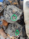
My CUCV had both alternators identical. They were both isolated ground, look for plastic insulators around the circled stud. Driver's side alternator gets negative pole connected to engine block for 12V. Passenger side alternator gets negative pole connected to 12V positive terminal for 24V. You can use a standard alternator in driver's side location but passenger side must be isolated ground.
 

Attachments

Keith_J

Well-known member
3,657
1,323
113
Location
Schertz TX
I've bench tested. You need the regulator plug pigtail , a small 12 volt light bulb and a decent 12 volt battery. Plus wire.

I chucked a rubber disk in an angle grinder to turn the pulley, direction matters not.

Plug the regulator pigtail into the alternator. The white or #1 wire is connected to the light bulb, the other contact on the bulb goes to 12 volt + on the battery. The red wire goes straight to the battery +. Connect the negative battery terminal to the negative on the alternator.

The light bulb should illuminate, meaning the rotor has bootstrap voltage for the magnetic field. Now turn the alternator with a pull cord, rubber grinder wheel or even a stationary bicycle. Needs to turn at least 1500 RPM, 2000 is better.

The light should go out. This shows diode trio is functional, sending power to the regulator which then generates more than battery voltage.

Next, measure output voltage at the main output terminal. It should exceed battery voltage. Now connect the main output + to the battery. Now you will have a heavy load on the pulley. This should remain until battery is 14.6 to 14.8 volts. Less with higher temperature.

Small sparks connecting batteries are possible from radio frequency suppression capacitors. Lead terminal melting arcs are a problem, stop and don't become a burn victim. It takes two months to grow a single square inch of skin from a full thickness burn.

Check polarity. GM has good color coding of wires, purple is always starter, purple with a stripe is starter relay. The one sticky point is the right alternator. The main positive battery terminal connects to the 24 volt bus, top bar with a solid red color wire. This is the same as the back battery +. The alternator negative likewise connects to the front battery positive, wire color is red with white stripe. So if you have memorized wire colors, grab the TM.

If wire connections are to the TM and you still are sparky, you probably fried the main bridge rectifier. This is a six pack of diodes, converting three phase delta alternating current at 14.6 volts into a nearly ripple free direct current.
 

Mullaney

Well-known member
Steel Soldiers Supporter
Supporting Vendor
7,716
19,766
113
Location
Charlotte NC
I've bench tested. You need the regulator plug pigtail , a small 12 volt light bulb and a decent 12 volt battery. Plus wire.

I chucked a rubber disk in an angle grinder to turn the pulley, direction matters not.

Plug the regulator pigtail into the alternator. The white or #1 wire is connected to the light bulb, the other contact on the bulb goes to 12 volt + on the battery. The red wire goes straight to the battery +. Connect the negative battery terminal to the negative on the alternator.

The light bulb should illuminate, meaning the rotor has bootstrap voltage for the magnetic field. Now turn the alternator with a pull cord, rubber grinder wheel or even a stationary bicycle. Needs to turn at least 1500 RPM, 2000 is better.

The light should go out. This shows diode trio is functional, sending power to the regulator which then generates more than battery voltage.

Next, measure output voltage at the main output terminal. It should exceed battery voltage. Now connect the main output + to the battery. Now you will have a heavy load on the pulley. This should remain until battery is 14.6 to 14.8 volts. Less with higher temperature.

Small sparks connecting batteries are possible from radio frequency suppression capacitors. Lead terminal melting arcs are a problem, stop and don't become a burn victim. It takes two months to grow a single square inch of skin from a full thickness burn.

Check polarity. GM has good color coding of wires, purple is always starter, purple with a stripe is starter relay. The one sticky point is the right alternator. The main positive battery terminal connects to the 24 volt bus, top bar with a solid red color wire. This is the same as the back battery +. The alternator negative likewise connects to the front battery positive, wire color is red with white stripe. So if you have memorized wire colors, grab the TM.

If wire connections are to the TM and you still are sparky, you probably fried the main bridge rectifier. This is a six pack of diodes, converting three phase delta alternating current at 14.6 volts into a nearly ripple free direct current.
.
Nice testing writeup @Keith_J !
 
Top