• Steel Soldiers now has a few new forums, read more about it at: New Munitions Forums!

  • Microsoft MSN, Live, Hotmail, Outlook email users may not be receiving emails. We are working to resolve this issue. Please add support@steelsoldiers.com to your trusted contacts.

Bringing back to life a 2009 HMMWV M1165A1 from GovPlanet - total newbie, please help...

T9000

Well-known member
Steel Soldiers Supporter
488
367
63
Location
California
The guy i spoke with at Centramatics drives an H1. I dont recall his name. That is just a general product page. Maybe our tires/wherl are different due to the 150 plus pound weight.
I took that screenshot from the bottom of the H1 page, it would be very misleading if it’s not accurate:


I will double check with them and let you know.
 

T9000

Well-known member
Steel Soldiers Supporter
488
367
63
Location
California
That hose going up the intake stack should be plugged to the end of a little metal canister sitting behind the coolant overflow tank. It is for the fuel tank.
A centramatic rep told me that the tires should be balance when using their product.
Balancemasters are the product that instructs us to remove weights.
I checked and the fuel vent it is going to the metal tube, going all the way up in the stack, and the plastic tube next to it (you may have to zoom in the picture as it may appear to be only the black plastic tube, but there is a second metallic tube, same tan color as the breather and it is very close to it, but you can see there are two clamps for the two tubes) is connected only to the steering pump vent (not to the rest of the truck vent system), different than the manual, right? Any idea why?
Vent Lines 2.jpg
 
Last edited:

Action

Well-known member
3,576
1,557
113
Location
East Tennessee
The fuel vent hose is correct. To the metal tube.
By “steerimp pump vent”, are you talking about the black can on top of the engine? If so, I can only guess it was done because soldier A kept overfilling the system, which could send fluid into the vent hose.
if at the correct level, the truck would need to be almost straight up or down. Or on its side, to get fluid in the vent line.
 

T9000

Well-known member
Steel Soldiers Supporter
488
367
63
Location
California
That hose going up the intake stack should be plugged to the end of a little metal canister sitting behind the coolant overflow tank. It is for the fuel tank.
A centramatic rep told me that the tires should be balance when using their product.
Balancemasters are the product that instructs us to remove weights.
I received the answer back from Centramatic saying that there is no need to pre-balance H1s, they have 12 ounces built in. If the tires require more than 12 ounces, then it would need to be pre-balanced. How much weight did they use on your tires or on the average?
 
Last edited:

Action

Well-known member
3,576
1,557
113
Location
East Tennessee
I received the answer back from Centramatic saying that there is no need to pre-balance H1s, they have 12 ounces built in. If the tires require more than 12 ounces, then it would need to be pre-balanced. How much weight did they use on your tires or on the average?
Ive had 18-20 on them before. Lots of 1-4 stick ons.
I would have rather bought Balancemasters at the time but couldnt spare that much cash. They compensate for more weight with mercury.
 
Last edited:

T9000

Well-known member
Steel Soldiers Supporter
488
367
63
Location
California
Ive has 18-20 on them before. Lots of 1-4 stick ons.
Then the BalanceMaster HUM206R sound like a better solution as they can balance up to 30oz. It cost a little more (450 vs 300) but it’s a better fit. I will look into those, have you heard anything not good about them on a HMMWV?
 

Action

Well-known member
3,576
1,557
113
Location
East Tennessee
Then the BalanceMaster HUM206R sound like a better solution as they can balance up to 30oz. It cost a little more (450 vs 300) but it’s a better fit. I will look into those, have you heard anything not good about them on a HMMWV?
2 of my 4 centramatics leaked all the fluid out on my rims. They were quickly replaced under warranty. One had the sealant line about 2” from the seam !
 

T9000

Well-known member
Steel Soldiers Supporter
488
367
63
Location
California
2 of my 4 centramatics leaked all the fluid out on my rims. They were quickly replaced under warranty. One had the sealant line about 2” from the seam !
How about the Balance Masters? Any feedback about those as I am looking into getting some? The warranty seems better too, Lifetime vs 5 years on Centramatics.
 

T9000

Well-known member
Steel Soldiers Supporter
488
367
63
Location
California
The fuel vent hose is correct. To the metal tube.
By “steerimp pump vent”, are you talking about the black can on top of the engine? If so, I can only guess it was done because soldier A kept overfilling the system, which could send fluid into the vent hose.
if at the correct level, the truck would need to be almost straight up or down. Or on its side, to get fluid in the vent line.
I have those two vent lines not connected together (one coming from the air cleaner and the other from the truck vent system) and in the manual diagram it shows them joined, would you know what that box in the drawing is (with the red question mark)? Is it just a barb union? It seems it is brought inside the cabin for some reason? It looks like it's connected to the air restriction gauge? But that has only one connector, and it is for another type of hose, the rubber one which I already connected.

Venting.jpg
 

Action

Well-known member
3,576
1,557
113
Location
East Tennessee
I have those two vent lines not connected together (one coming from the air cleaner and the other from the truck vent system) and in the manual diagram it shows them joined, would you know what that box in the drawing is (with the red question mark)? Is it just a barb union? It seems it is brought inside the cabin for some reason? It looks like it's connected to the air restriction gauge? But that has only one connector, and it is for another type of hose, the rubber one which I already connected.

View attachment 853137
I wouldnt use that diagram for your truck. Your fuel vents do not touch other vents. That diagram doesn’t have fuel tank or GFD vents on it.
The parts book lists the length of each hose piece. With the known lengths and the serice TM, the vents will fall into place. Without being there, i cant help much more. Maybe someone else can.
 

T9000

Well-known member
Steel Soldiers Supporter
488
367
63
Location
California
I wouldnt use that diagram for your truck. Your fuel vents do not touch other vents. That diagram doesn’t have fuel tank or GFD vents on it.
The parts book lists the length of each hose piece. With the known lengths and the serice TM, the vents will fall into place. Without being there, i cant help much more. Maybe someone else can.
I found a better diagram that I think it shows that indeed the two disconnected tubes (one is 62" - to the air cleaner - and the other one that comes from down below close to the geared fan is about 68" inches long - it seems that should be shorter in the drawing but it is routed the long way around, from below - they were possibly longer and maybe were cut during the demil process) should be somehow connected together to the Central Vent System. And indeed, this diagram shows that the Fuel Vent lines are separated from the central vent lines:
Central Venting 1.jpg

In my truck the lines are disconnected where I marked "Not Connected" and there is no indication that it was modified. There are two additional vent line missing from this drawing and didn't add it to keep it cleaner - one being the geared fan and the other coming from below, around the area where it says "Not Connected" all the way across to the top, to a tank in the area on the driver side that contains what I believe is called hydro-boost/ master cylinder.
I think it would be OK to connect those two ends together for now until I install the fording valve?
 
Last edited:

Action

Well-known member
3,576
1,557
113
Location
East Tennessee
I found a better diagram that I think it shows that indeed the two disconnected tubes (one is 62" - to the air cleaner - and the other one that comes from down below close to the geared fan is about 68" inches long - it seems that should be shorter in the drawing but it is routed the long way around, from below - they were possibly longer and maybe were cut during the demil process) should be somehow connected together to the Central Vent System. And indeed, this diagram shows that the Fuel Vent lines are separated from the central vent lines:
View attachment 853162

In my truck the lines are disconnected where I marked "Not Connected" and there is no indication that it was modified. There are two additional vent line missing from this drawing and didn't add it to keep it cleaner - one being the geared fan and the other coming from below, around the area where it says "Not Connected" all the way across to the top, to a tank in the area on the driver side that contains what I believe is called hydro-boost/ master cylinder.
I think it would be OK to connect those two ends together for now until I install the fording valve?
As stated earlier, the rubber hose by the front bumper connects to the cdr valve.
The fording valve has 3 hoses on it, not one like in your drawing. I think one to cdr valve, one to air cleaner, and one to the system.
The hydroboost vent just routes down the wheelweel to nothing. The master cylinder hooks into everything else.
There should not be a black tube hanging on the side of the fording intake.
The rubber hose on air filter can hooks to air restriction gauge.
 

T9000

Well-known member
Steel Soldiers Supporter
488
367
63
Location
California
As stated earlier, the rubber hose by the front bumper connects to the cdr valve.
The fording valve has 3 hoses on it, not one like in your drawing. I think one to cdr valve, one to air cleaner, and one to the system.
The hydroboost vent just routes down the wheelweel to nothing. The master cylinder hooks into everything else.
There should not be a black tube hanging on the side of the fording intake.
The rubber hose on air filter can hooks to air restriction gauge.
Thanks
 
Last edited:

T9000

Well-known member
Steel Soldiers Supporter
488
367
63
Location
California
Just a quick update, I ordered the fording kit parts above, the Balancemasters and will DIY the remaining tires, 3 plus spare as I also got a Rhino spare tire carrier, which will install soon, after getting all the vent system correctly so no dirt or water could get in like many of you mentioned.
The next step will be getting the AC going, I am sure it will have its own set of surprises lol.
Oh, I also got a new serpentine belt and when I replace it, will try to remove the AC compressor (without taking off the hoses, like Action said) and fix the last remaining leak on the 1/4" return line - :)
I am very grateful for everyone's input and help, thank you again!
 
Last edited:

T9000

Well-known member
Steel Soldiers Supporter
488
367
63
Location
California
In preparation for installing the new incoming CDR valve, I was checking the hoses and noticed that the one connected to the air horn had some movement.
It eventually came out relatively easily and even as I washed the engine multiple times before to remove the huge amounts of sand and caked gunk, there is still some left in cracks and creases, and when the CDR hose metal air horn adapter came out, I think some dirt fell, maybe in the air horn opening., circled in the picture:
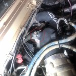
AirHorn1.jpg

I feel worried about the potential dirt that maybe fell in the air horn opening and was thinking to remove it and clean it before starting the engine.
Any potential problems with doing that? I am planning to cover the air horn opening while cleaning it so other dirt doesn't get in.
Or I was thinking to make a vacuum tubing adapter with a 90 degrees bend at the end and insert it to suck and potential dirt from inside? I am debating how much dirt may fall in when I remove the air horn as it may be caked around the hose clamps and trying to avoid making a bad situation, worse.

After cleaning it, I was thinking to use some silicone tape to make it a tighter, more sealed fit. The manual calls for using adhesive in order to seal the adapter?
 
Last edited:

Action

Well-known member
3,576
1,557
113
Location
East Tennessee
Why wouldnt you just remove the big rubber intake hose and stick your hand or shopvac hose into the air horn?
Have fun replacing the serpentine belt on your a1. You have to disconnect one end of the GFD driveshaft. IIRC
You are checking with AMG and GP about any change to vent lines on tan trucks? Lol. Let us know how that goes.
 

T9000

Well-known member
Steel Soldiers Supporter
488
367
63
Location
California
Why wouldnt you just remove the big rubber intake hose and stick your hand or shopvac hose into the air horn?
Have fun replacing the serpentine belt on your a1. You have to disconnect one end of the GFD driveshaft. IIRC
You are checking with AMG and GP about any change to vent lines on tan trucks? Lol. Let us know how that goes.
Yes, you are right, I did go in the air horn thru the big rubber intake hose and while it is off I am thinking to replace the air cleaner canister with the new one I got that has that rubber boot/ vent at the bottom.
I typed those thoughts in real time and was frustrated about the dirt that got in and wasn't thinking too clearly at 1AM :)

Getting the belt in thru the the geared fan seems to be the path of least resistance just by looking at it, I didn't check the manual yet, not sure when I will get to it, it's not a priority like the vent system.

Yes, I will let you know about the response I get, one texted back that they will send a diagram and the other is looking into it.

How about the water fording system connections in the diagram above in relationship to my truck, is that about right?
 

T9000

Well-known member
Steel Soldiers Supporter
488
367
63
Location
California
Why wouldnt you just remove the big rubber intake hose and stick your hand or shopvac hose into the air horn?
Have fun replacing the serpentine belt on your a1. You have to disconnect one end of the GFD driveshaft. IIRC
You are checking with AMG and GP about any change to vent lines on tan trucks? Lol. Let us know how that goes.
It's confirmed that indeed the vent tube going up the stack is a factory modification.
 
Last edited:

Action

Well-known member
3,576
1,557
113
Location
East Tennessee
It's confirmed that indeed the vent tube going up the stack is a factory modification.
If that is how you phrased the question to AMG, then of course the vent tube going up the stack is factory. It is for the fuel vent. If you got an email from an actual AMG tech, did they say why?
 

T9000

Well-known member
Steel Soldiers Supporter
488
367
63
Location
California
If that is how you phrased the question to AMG, then of course the vent tube going up the stack is factory. It is for the fuel vent. If you got an email from an actual AMG tech, did they say why?
It is done on 2008 and newer units without the air pre-cleaner option.
 
Last edited:
Top
AdBlock Detected

We get it, advertisements are annoying!

Sure, ad-blocking software does a great job at blocking ads, but it also blocks useful features of our website like our supporting vendors. Their ads help keep Steel Soldiers going. Please consider disabling your ad blockers for the site. Thanks!

I've Disabled AdBlock
No Thanks