• Steel Soldiers now has a few new forums, read more about it at: New Munitions Forums!

  • Microsoft MSN, Live, Hotmail, Outlook email users may not be receiving emails. We are working to resolve this issue. Please add support@steelsoldiers.com to your trusted contacts.

Civilizing the MEP-002A

3dAngus

Well-known member
4,719
101
63
Location
Perry, Ga.
I don't get it.

What was the problem before this massive amount of work was involved.
And why would you want to remove the manual throttle control.
 
Last edited:

Craig A Tull

New member
94
0
0
Location
Papalote TX
One of the connectors between the gen head and reconnection box was toast, this generator is going to be operated by a non technical person and the hand throttle was just another item that could be screwed up and is just not necessary, no other generator I have ever worked on but the military versions had hand throttles (also the freq. meter is another area where allot of folks have issues, without the hand throttle it is not needed at all and with the hand throttle it is absolutely necessary), also I wanted her to have a spare regulator and the way I laid out the harness anyone can replace the regulator, also contrary to what some say allot of folks have issues with the cvt-1, phase switch and the complex regulator scheme and it is the overwhelming majority of problems with the MEPs, and it is just not necessary if one only needs single phase. Again I am not advocating anyone do the mods just showing what can be done if necessary or if desired. One of the deficiencies I noticed was the inability to measure the current on both what would be L1 and L2 (actually L1 and L3 on the mep) the way I set this one up both legs can be simultaneously monitored, when load testing this MEP the first thing I noticed was a huge imbalance of loads here on my ranch between L1 and L2, I was pulling about 30 amps on L1 and 2.5 amps on L2, simply reversing the legs to a couple of my out buildings got it much closer to balanced.
Craig
 
Last edited:

3dAngus

Well-known member
4,719
101
63
Location
Perry, Ga.
How do you expect to maintain frequency via load condition without the manual speed control?
Even if you fix it permanently based on current load, this does not take into consideration wear and tear of the gen set itself.

You would be better off just fixing the connector and removing the voltage selector switch after it is set to the proper position, then leaving the rest alone. You can cut the stem off the voltage selector switch with bolt cutters so it cannot be changed.

From Tech manual TM 5-6115-584-12

Check frequency on frequency meter on control panel and
adjust governor if necessary, using speed control.
Frequency meter should read 61.5 with no load. Pulling
speed control knob out will increase frequency, pushing speed control knob in will decrease frequency.Text h. Place ammenter-volmeter transfer switch in
For fine-control turn knob CW to increase and CCW
to decrease
 

Craig A Tull

New member
94
0
0
Location
Papalote TX
That is not an issue, I maintained a pile of 12.5JC gen sets for twenty years on our microwave system before they were replaced, they have the same basic engine as the MEP only on natural gas or LPG, same gov. and set up just like I did this MEP, I may have "touched" up the governors maybe once in that twenty years, this MEP runs about 61 unloaded to around 58.5 fully loaded well within the industry standard of + - 5% as read on my Fluke meter, people are WAY too anal about frequency as I said NO other gen sets but the military ones I have seen have the ability for just anyone to change frequency and somehow the rest seem to do just fine.
I do not agree that "just pulling the knob" would be better, I would have had to acquire and replace the two connectors that were fried and then I would still have all that complex circuitry to fail, look at the schematic the only things that can fail are the regulator and the gen head itself as far as the generator side goes, and the spare regulator can be installed in 5 minuets. ALL of the work I have done is less that it would have taken to replace the connectors, so I am sorry to disagree General but you are WAY wrong on this issue.
 

Craig A Tull

New member
94
0
0
Location
Papalote TX
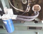
Oil filter

Oil filter.jpg
My late brother in-law Leon Linton was one of the most mechanically capable men I have ever known, he worked for 6 years on the North Slope, could build a rotary table out of an old banjo rear end and the most amazing thing I ever saw him do was take a torch and a rag soaked with motor oil and straiten a bent ram on a hydraulic cylinder, over thirty years ago he convinced me of the virtues of pre-filling oil filters, not only was there a delay in getting pressurized oil into the system it actually pushed what oil was in the system out with the air in front of the "new" oil. Now of course I do not have any clinical studies to prove there is ANY difference but I just have a "thing" about sideways mounted filters, I also wanted to add as much oil capacity as practical by using the "two" quart spin on filter which would make the real or imaginary issue of oil delivery delay even worse, so here is my idea of a solution. First I purchased the spin on adapter kit from Speddmon, very nice machine work fits perfectly, added a Fram HPK5 filter remote adapter and a Wix 33123 remote filter housing, I have a Weatherhead hydraulic hose crimper and plenty of stock so the hoses were no problem, now the mep takes 5 quarts of oil to fill, and yes he was my sisters husband so this is also in some small way a tribute to him.
 

3dAngus

Well-known member
4,719
101
63
Location
Perry, Ga.
OK, sorry about that, as I said, I just don't understand.
I bought a MEP-002 in perfect working order for $500 last week without batteries and if it had the issues yours had I would have scrapped it, but that's me.
You seem to have a good working knowledge of how these things work and what you want out of it. I'm happy for you. Go for it.
I would not recommend these kinds of things for the novice however. It can be very dangerous if not done right.
 

Craig A Tull

New member
94
0
0
Location
Papalote TX
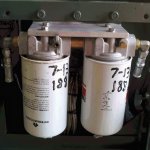
Fuel filters

Of course I wanted to replace the fuel filters with spin on filters, the primary filter is also a water separator and the secondary catches any small stuff that gets by the primary, I taped both discharge sides of the filter housings and installed drain cocks to aid in trouble shooting any fuel issues but then decided the the valve on the secondary added a risk of contamination getting past both filters and directly into the injection pump so I removed it and installed a plug, I made the mounting brackets for both oil and fuel filters out of aluminum bottom angle off of some old relay racks.Fuel filters.jpg
 

Craig A Tull

New member
94
0
0
Location
Papalote TX
No problemo General, I am surprised how cheap these go for in some parts of the country, you could not get a cannibalized unit that was dropped from a helicopter then run over by a truck for $500.00 down here.
Craig
 
Last edited:

Craig A Tull

New member
94
0
0
Location
Papalote TX
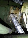
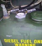
Fuel Lines

This unit was abandoned for many years, the fuel tank was corroded out and like just about every MEP I see the fuel lines were petrified just waiting for the opportunity to crack and leak, most of the fittings on the MEP are AN-5, the return line is AN-4 same as JIC for all practical purposes, so I replace all the lines with 100R2AT two wire hose, I checked with the manufacture and the response I got was "our hose is compatible with all petroleum based fluids" so most of the connectors are 04-05 (1/4" hose 5/16 JIC) as it tuned out the return fitting at the fuel tank was stripped so I used one of the extra 5/16 fittings from the fuel filters and had to remake a hose that was 5/16 (04-05)on one end and 1/4 (04-04) on the other, I also used one of the fittings from the fuel filters to replace the really bastardized fuel lines feeding the injection pump, I mean it went from AN to pipe to reverse flair back to pipe, what a mess.pump.jpgfuel tank.02.jpg
 
Last edited:

Craig A Tull

New member
94
0
0
Location
Papalote TX
Metering and regulation

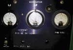
As shown above I replaced everything on the generator side but the gen head itself, I did re-use the volt meter, the only good ol made in the USA military meters I could find that "fit" the bill was some 300A scaled 5A full scale meters, so I picked up some 30A/5A current transformers and voila just divide by ten, reads perfectly compared to a Fluke clamp on meter, OK so I am not an artist and I could not find a brayer small enough so I tried to use a small foam roller with not much success, I will search for a brayer and my next project will look much better, good news is I got my $20.00 stencil machine working OKregulator.jpgmeter.jpg

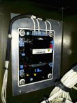
As you can see anyone can replace the regulator as I did my best to make it fool proof (I cut the center terminal #6 off of the spare regulator) OK load testing,,, I load tested for over 24 hrs, I used both the Flight Systems SX-460 ($170.00 w/sh) and a Chicomm clone (about SIX for $170.00 w/sh from China) and could not see any operational difference they both regulated the same, I did "load" the field leads to see how much voltage each required to "start up" and the F. S. unit was more sensitive requiring only about 5V to start and the Chicomm unit needed about 8 volts to start, the MEP was making about 11 volts unloaded so both regulators started up just fine, that is the 5A regulator power breaker in the hole that had the meter switch. I had it loaded at or just above 30 amps at times and it did not seem to mind the overload at all but of course would not recommend loading it like that for long periods of time, really nice being able to monitor both legs at the same time.
So there you have it, MY idea of an improved hopefully more reliable single phase only MEP-002A. I will be delivering this down by Concan at my sisters tomorrow, then on to the next project, I just received a depot rebuilt MEP-003A engine and am going to mate it to one of the 12.5JC single phase gen heads I have (not stupid grabbed everyone I could get when we pulled them out of service)
OBTW the Generac units that were put in to replace those 25 year old Onans starting about 7-8 years ago have all been junked and "they" think Kohler is the way to go now...
 
Last edited:

JOHNPFD1

New member
27
1
1
Location
pawtucket, ri
Craig, have you thought about posting some pics of all 4 sides of the generator and possibly posting step by step instructions to be able to do my own Civilizing of my MEP-002a? Thanks John
 

Craig A Tull

New member
94
0
0
Location
Papalote TX
Well that 002 has been deployed in the field and I don't have covenant access to it, I will try to get some more pictures on my next trip to my sisters but that only happens about once a year, there are 4 separate systems that were "civilized" first is the electrical, removing the reconnection box and regulator and replacing it with a 4 wire (SX460) regulator and duel amp meters. second was the fuel system, removing the canister type filters and replacing them with spin on and all new hoses. Third was the oil filter and forth was the governor mod, removing the throttle cable, If I get another MEP I will do the mods and try to document the project, at this time I only have one left and am keeping it stock as I have some three phase radio equipment that I can only power with that MEP. Most of the information needed is already in this thread that is needed and I would be happy to answer any questions.


I will try to give a basic overview of the electrical here, I am not responsible for any mods that anyone decides to try, this should not be attempted by anyone not familiar with electrical safety and a working knowledge of electrical circuits including protection devices and the fed. state and local electrical codes..

1 remove the reconnection box and cut the plugs off of the harness that was connected to the recon. box
2 there are twelve large and two small (field) wires coming out of the gen head, the twelve larger ones are all marked T1 etc. along the wires, connect them as in the schematic in post #9, notice T8,T10 and T2,T4 are just connected together, these were just twisted together soldered, taped and buried in the harness, one of the two can be seen in the picture in post #13 this leaves only 8 wires to terminate on the terminal block shown in post #13.
3 I used the wires left from cutting the harness loose to route the two field wires and the three voltage "sample" wires (shown in post #13)into the control box along with the four wires from the current transformers to the amp meters in the control box. I just used an ohm meter to trace them into the control box, when I removed the old regulator I traced and removed all the wires that ran from the regulator to the terminal strips in the control box,
route the 240V sample wires (through a 5 amp fuse or breaker) and the two field wires to the regulator as shown in post #19, install and wire the two current transformers and amp meters, wire the 240V "sample" wires to the volt meter (same as the 240V wires going to the regulator) Notice that I did route three "sample" wires into the control box, one ea. of the two 120V legs and the ground or neutral, I did not use the neutral as the volt meter and the regulator only required the 240V (L1+L2) so that ground or neutral will not be seen on the schematic in post #19.
Clear as mud?
Craig
 
Last edited:

Ray70

Well-known member
2,562
5,795
113
Location
West greenwich/RI
John, Welcome to the forum, glad you decided to join. These guys are a wealth of knowledge, you will find anything you need to know about your MEP-002A on here. Ray.
 

Chrkjones

New member
4
0
0
Location
Thomasville, Ga
Are the cvt1's in a mep-002a different from a cvt1 in a 5kw 400 cps? Google, 400 cps distribution box and click image. Scroll down to pics and read will not work in mep-002a but most parts will work. I just bought that box and installed the cvt1 in my mep-002a and just fried it after 10 seconds. pn 's are different. 5950-01-100-8400(400 cps) vs 5935-01-049-9850 my original
 

Triple Jim

Well-known member
1,375
286
83
Location
North Carolina
400 Hz transformers normally have a lot less iron in them than 60 Hz transformers. The resulting lower weight of transformers and motors is the main reason airplanes standardized on 400 Hz. The small iron cores mean they will get hot quickly if run at 60 Hz. That doesn't mean there isn't something wrong that will also fry the 60 Hz version of CVT1 and CT1, but the 400 Hz transformers were doomed in any case.
 
Top
AdBlock Detected

We get it, advertisements are annoying!

Sure, ad-blocking software does a great job at blocking ads, but it also blocks useful features of our website like our supporting vendors. Their ads help keep Steel Soldiers going. Please consider disabling your ad blockers for the site. Thanks!

I've Disabled AdBlock
No Thanks