• Steel Soldiers now has a few new forums, read more about it at: New Munitions Forums!

  • Microsoft MSN, Live, Hotmail, Outlook email users may not be receiving emails. We are working to resolve this issue. Please add support@steelsoldiers.com to your trusted contacts.

converting 24v truck to 12v trailer

Big Red Bull

New member
50
25
0
Location
Grandy, NC
I got this one :funny:I have plenty of hammers. I just don't know how to use them:cookoo: I wound up going to pneumatic nail guns. Maybe I could just pull the safety and shoot the **** out of it!!!!!!
 

Big Red Bull

New member
50
25
0
Location
Grandy, NC
Ok what if I added 2 deep cycle batteries to run my lights brakes cig lighter and radio and used an auto battery charger at night to recharge them. I also have a gen set for my business trailer that I could plug the charger into riding down the road. This is NOT my ideal way of doing it but it would work.

I did order one of these convertors Military Lighting adapter, 24vdc to 12vdc Brand new in the box - Steel Soldiers::Military Vehicles Supersite I'm hoping I can find a spare 12v wire in the box that I can run into the cab for the brake controller. I also ordered a Max Brake controller. here is the web site MaxBrake Brake Controller
 

Attachments

trukhead

New member
725
5
0
Location
dane/wi
24 volts to 12 vollts

A CUCV is a 83-86 1.25 ton 4x4 Chevy truck the Military used with numbers such as M1008, M1028 etc...
The resistor I am referring to is the big one aft of the engine, bolted to the firewall that steps down 24 volts to 12 volts to operate the glow plug circuit of the truck.
These trucks use 2 12 volt batteries and respective 12 volt alternators connected in series to generate 24 volts to run the starter and the 24 volt tap-off as well as the trailer hookup. It is important to remeber that the altenators are isolated ground and operate in series as well.
Under the dash the truck is still 12 volts and they tap off 12 volts from a battery for that.
The glow plug circuit however is powered off of the 24 volt tap for various reasons explained in other threads far better than I can explain.

My thought is this resistor might be enough or perhaps two of these in parallel might be enough to operate the current and provide the 12 volts to operate the brake controller, but you need to take the measurements and do the calculations to determine this for yourself as this is just the raw idea.

If I recall resistors in parallel reduce current and resistors in series reduce voltage.

I am curious and will dig out my circuit analysis text book and take measurements from an electric axle brake setup t determine if this will work because my M35A3 is 24 volt as well and it would be handy to have it operate an electric trailer brake setup as well.

Disclaimer: I have no idea if this will work and have not done any calculations or taken any measurements to verify if this will work and take no responsibility for any one's(') actions acting on this post in any way shape or form applying this equipment described above in this post to operate anything in the spirit of this or any other thread on this SS site or in this universe!

2cents
 

Commander5993

Active member
Steel Soldiers Supporter
(warning: long post...)

Hi, I don't mean to resurrect an old thread, but at the same time I don't want to start a new thread for the same subject.

I have also been searching and reading up on being able to pull a civy trailer with an A3 Deuce. I have read the cheapest way is to change the 12v bulbs in the trailer out with 24v bulbs. Which would be fine, except I may be pulling different trailers, and a civy truck may be pulling the same trailers as well, on different occasions.

So I have been looking for a way to modify the deuce to be able to pull a civy trailer with-out modifying the trailer. I also want to have a setup which will be able to use trailer brakes. However I have never needed nor used trailer brakes before, so throwing this into the mix is complicating things further... at least for me. Still searching for more info on trailer brakes and controllers and how they are setup.
So I apologize if I ask some dumb questions about this.

I do know that a trailer brake controller will be needed, not sure how that is going to hook up with the voltage/signal converter and trailer being 12 volt and the truck being 24 volt. I think I have found a 24 volt to 12 volt trailer power converter.

I am also going to add a separate 12 volt alternator/battery power system to the truck, however this does not connect in with the trucks tail/turn/brake signals. But it could be used as a 12 volt power source, if required. I read about the relay signal conversion, but I don't think I want to go that route unless I have to.

I read what Scout stated earlier in this thread "...
an electric brake magnet draws 3 amps. A two axle trailer with brakes on all four wheels is a 12 amp draw..." and this would describe the type of trailer that we are looking to buy right now. As we are looking for a 7' x 14' or 7' x 16' box tandem box trailer with brakes.

So with Scouts amp calculations, I started looking for an 24 volt to 12 volt converter with at least 12+ amps. I think I have found one that will work, but again I'm not sure how this will connect into a trailer brake controller. The box that I found is an

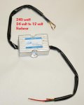
GSL ELECTRONICS MCR-240 Watt, VOLTAGE REDUCER 24-12V, Four CIRCUIT


Now, I think 240 Watts converts into 20 amps... ?? (no I'm not that smart, I used an online "watt to amp" calculation converter) If this is correct, it should be enough amps, with a few additional to spare. Here are the specs of the converter which are located on this website - link Attached is a photo of the converter box, but in the photo it is showing 120 watt version, but the 240 watt looks identical.


So has anyone used or had any experience with one of these? Does this sound like it will work with a 12v Tandem Trailer with brakes?

Thanks for Any and All help!


Voltage Converter Box Specs Below:


MCR-240 GSL Electronics - Voltage Reducer 24-12V 240W 4 Ciruit Waterproof
Multi circuit reducers are designed specifically for applications with incandescent & LED lighting for caravans, box trailers and other automotive vehicles.

When choosing which model to use you should determine the load required to be carried by each circuit as accurately as possible and choose the model which has a capacity of 10-15% above the estimated current needed to allow for wiring resistance in trailers.

The MCR 120 and MCR 240 series are designed for caravans, box trailers and other small trailers where the length of cable does not exceed 6m.

Product MCR-240
Circuits 4
Power Rating [Watts] 240W
Waterproofing Encapsulated
Dimensions [LxWxH] 73mm x 92mm x 31.5mm
 

Attachments

sierra117

Member
188
1
18
Location
Isanti, MN
I used a 24 to 12 volt power converter. The power runs to the back of the truck and through three relays (2 for turn signals and one for the running lights) individually and out to the civy plug. I then ran spliced in wires from the nato plug to relay that basically power the relay and allows the 12 volts through to the plug
 

Attachments

mikew

Member
454
8
18
Location
edmond, ok
Here's a link to the ones I've been building, they are very similar to the one Sierra117 made:
Civi Trailer Lights

The problem with running trailer brakes off a voltage converter isn't the power required to fully engage them, about 6 or so amps per axle, but the surge current when they are first engaged which can be many times the operating current.

You might be able to get a proportional controller to work because it should control the surge current, but I'd talk to the manufacturer to confirm the peak current requirements. There is an outfit in Australia that has a 24v brake controller, but it's pricey!

Operating the brakes and lights via relays from a 12 volt alternator, no problem.
 

Commander5993

Active member
Steel Soldiers Supporter
I used a 24 to 12 volt power converter. The power runs to the back of the truck and through three relays (2 for turn signals and one for the running lights) individually and out to the civy plug. I then ran spliced in wires from the nato plug to relay that basically power the relay and allows the 12 volts through to the plug

Hummm.... I will already have a 12 volt power supply with the 12v Alt/Battery system... That's actually a pretty simple setup. Not to sure about how to incorporate a brake controller, but it shouldn't be too hard.

Happen to remember what # of relay that you used? Or does it just have to be able to carry the voltage/amps?

Thanks for the Post!
 

Commander5993

Active member
Steel Soldiers Supporter
Here's a link to the ones I've been building, they are very similar to the one Sierra117 made:
Civi Trailer Lights
Nice looking unit!

The problem with running trailer brakes off a voltage converter isn't the power required to fully engage them, about 6 or so amps per axle, but the surge current when they are first engaged which can be many times the operating current.
Humm... didn't know about the surge current. Doesn't sound like the controller I found will work then, as it is only 20 amps total, which is only 8 amps more than required power.

You might be able to get a proportional controller to work because it should control the surge current, but I'd talk to the manufacturer to confirm the peak current requirements. There is an outfit in Australia that has a 24v brake controller, but it's pricey!
Yes, 24v stuff seems to be $$$! The converter that I was looking at was just under $150 bucks! And it was from australia too!

Operating the brakes and lights via relays from a 12 volt alternator, no problem.[/QUOTE]

Ok, so you're saying that an 12 volt alternator system (instead of the inverter you use), and then use relays to pick up the 24 volt signal, which would then activate the 12 volt power connection to the trailer - That is the best way to go?
How would this work/connect with a brake controller? Connect it into the 12 volt signal wire after the relays?


I'm already planning to have a separate 12 volt system on the truck, consisting of an 12 volt alternator and 3rd battery. So the 12 volt power will be available.

If I were to go this route, do you happen to know what relay # would I need?


Thanks for the Explanation! [thumbzup]
 

mikew

Member
454
8
18
Location
edmond, ok
Yep, three relays with 24v coils, like Sierra117 (do an E-Bay search for "24v relay", look for something like this: GPS GSM GPRS car tracker car alarm accessory Relay 24V | eBay A little searching will find you ones in the USA).

Trigger the relays with the 24v left and right stop/turn plus the tail signals going to the composite lights. Connect relays to your 12v source and use their outputs to drive the trailer lights. The 12v brake light circuit will connect to your brake controller to trigger it.
 

Commander5993

Active member
Steel Soldiers Supporter
I used a 24 to 12 volt power converter. The power runs to the back of the truck and through three relays (2 for turn signals and one for the running lights) individually and out to the civy plug. I then ran spliced in wires from the nato plug to relay that basically power the relay and allows the 12 volts through to the plug
Yep, three relays with 24v coils, like Sierra117 (do an E-Bay search for "24v relay", look for something like this: GPS GSM GPRS car tracker car alarm accessory Relay 24V | eBay A little searching will find you ones in the USA).

Trigger the relays with the 24v left and right stop/turn plus the tail signals going to the composite lights. Connect relays to your 12v source and use their outputs to drive the trailer lights. The 12v brake light circuit will connect to your brake controller to trigger it.
Now that I have heard it explained, seen how it is installed, and know what I am looking for, I think this is the way to go after all. It is less cost, seems easier to do, and if a relay ever goes bad, easy to fix. Thanks for the Help Guys! [thumbzup][thumbzup][thumbzup]
 

Big Red Bull

New member
50
25
0
Location
Grandy, NC
I'll tell you what I did and it worked for me. I have 4 batteries, 2 sets of 2. Each set is in series, then both sets are paralleled. Off of each set I split the load, 1 for running lights and brake lights. I added a toggle switch to the dash to turn the lights on, and added a momentary toggle to the floor board, spring loaded, connetcted to the brake pedal. This gives me running lights and brake lights. The other set I added the brake controller and blinkers. I got a 12v flasher and added momentary switches to the blinker handle. The brake controller was really easy, once I gave it power and connected the hydrolic line I just had to run the wires to the rear of the truck, take a 7 pin connector, wire everything in and I have everything. It may sound like quite a bit of work but it was the best way for me to understand it to do it while keeping the trailer original for pulling with other vehicles. And allowing me to use the truck to pull any 12v trailer from here on out. I use it everyday and have had no problems yet. Hope this helps
 

Commander5993

Active member
Steel Soldiers Supporter
Yep, get sockets for them too. Although 1/4" spade connectors will work also.

Great! Thanks! [thumbzup]
Yeah I like the sockets better than just using spades. More contained and the connections are more secure.

Thanks for all the help guys, I'll post my results when I get this done sometime over the next few weeks.
 
Last edited:

Commander5993

Active member
Steel Soldiers Supporter
Well, got the relays Ordered. Strangely enough though, that website didn't sell the relay socket....
But I was able to get the socket from Napa today, well only got 1 right now, but the other 3 on order will be in tomorrow.


So for those who are looking for the 24 volt relays for the 24 volt-to-12 volt trailer conversion. I found a 24volt relay at http://www.ase-supply.com (Excellent Customer Service!), the relay that I found is part #
CH-RC-200124-RN made in USA by Cole Hersee and can be found at this link for only $2.97 each!

Also the 5 slot relay socket can be purchased at Napa Part # EC23 (alternate #U11139)

I haven't installed these yet, but I will post my results with pics, once completed in a few weeks.

Update:
This relay Part # above is a 5 blade relay. But from what kc4wd has stated in the post below, a 4 pin relay can be used. If you use a 5 pin relay, pin 87 will not be used. In any case, the 5 pin relay will work just fine, and was the same price as the 4 pin relay as well.


------------
Update:
As I was making this post, and inserting the parts number for the relay. I started looking at the web page with the relay on it, and Realized I Had Ordered the Wrong Relay!! I accidentally ordered a 4 blade relay, instead of a 5 blade relay. The part number was only 1 digit Different!
I am very Glad that I caught this only minuets after placing my order.

So I called the company immediately, and a gentleman named Bob answered and I said, "Yeah I just placed an order through your website.."
Bob "Mr Smith?"
me "Uhhh... Yes that's me"
Bob "Yeah we're pulling your order right now"
me "Wow, that was fast"

Anyway, just glad I called when I did and caught the order before they finished processing. So he fixed the order with the right part number and all was good...

Well or so I thought... Bob called me back just now, and told me they only had 3 relays in stock, and that he would have to order the rest but it would be 10-14 days!! (I ordered 8 just to have extras). So I told him basically what I wanted to use it for, and he said he would check with some of the parts guys and see if there would be a different relay that would work for our "project".

Bob just called me back again (before I could even finish this post) and said they had found the correct relay for the job and that it would ship tonight!
And they have a Great Price too, the relays are only $2.97 each!

So I have to recommend this company,
http://www.ase-supply.com as with the experience I just had, they have Excellent Customer Service! And they carry a lot of other electrical type items too.
I have updated my original post above with the correct part # and Link.
 
Last edited:

kc4wd

Member
130
0
16
Location
Asheboro, NC
I've been reading this thread and maybe I missed it but, why must it be a 5 pin relay? As long as you get a normally open 4 pin relay it will work fine. I used 5 pin relays on mine just because that is what I had. On my 5 pin relay, I have a terminal I didn't use, pin 87 is normally closed and not used. Pin 87a is normally open.
 
Last edited:

Commander5993

Active member
Steel Soldiers Supporter
I've been reading this thread and maybe I missed it but, why must it be a 5 pin relay? As long as you get a normally open 4 pin relay it will work fine. I used 5 pin relays on mine just because that is what I had. On my 5 pin relay, I have a terminal I didn't use, pin 87 is normally closed and not used. Pin 87a is normally open.

I was wondering about if a 4 pin relay would work. But I thought I read on another thread that a 5 pin relay was required. But I haven't done the install yet, so I have no experience to verify. But I guess you answered that question. Oh well, the 5 pin relay was the same price, guess I'll just have an extra pin.

Humm... just had a thought. I wonder if you used a 5 pin relay, that you could use 1 relay for both brakes and tail lights? Connect the taillights to 87, and then connect the brakes through 87a...?? Sound reasonable?

As you can tell, I'm no electrician. Know the basics,and can usually repair stuff, but never had any reason to use relays for anything more than just replacing dead ones.


Thanks for the post!
 

kc4wd

Member
130
0
16
Location
Asheboro, NC
I'm gonna say no......1 relay for tail, 1 for left turn, 1 for right turn, Turn signals are the brake lights. So it would possably work for tail and brakes but, how would you do signals?
 

Commander5993

Active member
Steel Soldiers Supporter
I've been reading this thread and maybe I missed it but, why must it be a 5 pin relay? As long as you get a normally open 4 pin relay it will work fine. I used 5 pin relays on mine just because that is what I had. On my 5 pin relay, I have a terminal I didn't use, pin 87 is normally closed and not used. Pin 87a is normally open.

Updated my post above, and took out the part that a 5 pin relay was required, and put instead that a 4 pin relay could also be used.
Thanks for pointing that out kc4wd! [thumbzup]
 

kc4wd

Member
130
0
16
Location
Asheboro, NC
Hey, No Problem. If you want to use a trailer brake control, wire in another relay comming from the brake light switch at the master cyl.


By the way....in the link, in my signature about the NC rally, I am having a free siminar on 12v additions and trailer wire conversions on the deuce. So if anyone want to see this come to the rally. (shameless plug!)
 
Last edited:
Top
AdBlock Detected

We get it, advertisements are annoying!

Sure, ad-blocking software does a great job at blocking ads, but it also blocks useful features of our website like our supporting vendors. Their ads help keep Steel Soldiers going. Please consider disabling your ad blockers for the site. Thanks!

I've Disabled AdBlock
No Thanks