• Steel Soldiers now has a few new forums, read more about it at: New Munitions Forums!

  • Microsoft MSN, Live, Hotmail, Outlook email users may not be receiving emails. We are working to resolve this issue. Please add support@steelsoldiers.com to your trusted contacts.

Converting a 005A with a Digital Controller

peapvp

Well-known member
Steel Soldiers Supporter
1,159
1,344
113
Location
Basehor, KS
As announced in a separate post several weeks ago, Larry @Cowhunter and myself have started on converting his 005A to a MeBay DC-70DR MK II controller based system

we will update this thread here over the next several weeks

Larry and his 005A are based in Southern California and I am in Kansas City. I am doing this remotely.

Why are we doing this?

Larry had his 005A converted to single phase zigzag as per instruction videos on YouTube from one of our infamous members, to power his workshop primarily

Larry ran into the same issues as most other folks who did the single phase conversion, namely setting the output voltage to 240VAC between the two phases, winding up with two blown A11 static exciter voltage regulators.
I have repaired both and they are running fine now.

As a general piece of advice:

Because the A11 can be adjusted to 240VAC, which is pretty much the top end of regulation, doesn’t mean that they should be set that high.
The 004A / 005A / 006A are RATED for 208 VAC and so this A11 in all three units. The same goes for the Tactical Precise Version.

During the course of the A11 repairs, I realized that Larry’s cubicle has seen much better days as nature had delivered a pretty good beating on this nearly 50 year old piece of equipment.

So the idea was born to strip all the old electronics out and start fresh.

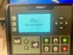
After evaluating several modern day controllers, like the British made Deepsea controllers, Larry decided to go with a more economically priced Controller from MeBay, bought on Amazon and shipped from China.

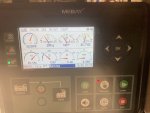
the DC 70 DR MK II costs just around $ 200

Larry then sent the controller to me for programming
IMG_2319.jpeg

IMG_2331.jpeg
 
Last edited:

peapvp

Well-known member
Steel Soldiers Supporter
1,159
1,344
113
Location
Basehor, KS
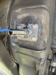
The first step was the installation of a MPU

We found a Cummins 3034572 MPU on Amazon for 25 Bucks.

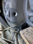
Larry then drilled two holes into the flywheel housing and installed the sensor on a plate, which made centering the sensor over flywheel real easy

IMG_4918.jpeg

75624282538__A69CE760-6945-45F9-AA4E-0EB7B0CF520C.jpeg

75624286931__352D9C5C-7FCF-4C0E-8BEF-90F66654D2B9.jpeg
IMG_4945.jpeg

the hole on the side is the “peephole”

we adjusted the gap to 0.021” which gives us a 1.3 VAC signal during crank
and a 20 VAC signal at 4.1 KHz @ 1800 rpm

the DC 70 can handle a signal from 0.5 VAC to 70 VAC up to 10 KHz

Task #1 finished
 

Guyfang

Moderator
Staff member
Moderator
17,491
25,872
113
Location
Burgkunstadt, Germany
OK, here is a tip. When we converted hundreds of gen sets to MPU's, later on in life, we ran into a problem.

1. The metal filings. We did not do a VERY good job of cleaning them out of the bell housing. Later, sometimes several times on the same set, one little piece of metal would be attracted to the MPU magnet, and would make contact between the MPU outer housing and the magnet. MPU will not function then.

We did not use a plate, and it looks like a good idea. The Army just measured and drilled. Worked every time, BUT once, that I know. The one time, the last thread through the bell housing had a burr. For the next 2 years, (YES, 2 years) no one could get the gen set to run. Why? well the burr, would not let the MPU screw down far enough to "See" the ring gear. Everyone screwed the MPU in, and tightened it up to bottom out.Then back it off a half turn. The burr was the bottom. So after 2 years of people sending this gen set from one shop to another, my shop found the problem. I like the Peep hole!
 

peapvp

Well-known member
Steel Soldiers Supporter
1,159
1,344
113
Location
Basehor, KS
We are moving on in our project and would like to update the interested reader.

The MeBay DC-70DR MK II controller has reconfigurable Analog Inputs for

Coolant Temp Sneor [AUX S1 TB# 17]
Oil Pressure Senosr [AUX S2 TB# 18]

AUX S3 TB# 19 and AUX S4 TB# E1 and can be assigned through the software via a USB Cable and a Laptop

We assigned AUX S3 TB#19 to the Fuel Level Gauge

The Analog Inputs can be scaled to fit the resistance vs the gauge level in up to 10 Increments

However, the maximum Resistance is limited to 999 Ohms

For the existing fuel level sending you unit ( 0 Ohms Empty to ~ 30 Ohms full) and the Oil Pressure Transducer (0 Ohm 0 PSI to ~ 24 Ohm 60 PSI)

This poses no problem and we can use the existing Transducers

However, the Coolant Temp Sensor does not drop below 1 KOhm until it reaches well over 200 F
We measured 1.013 KOhm @ 180F

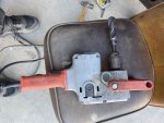
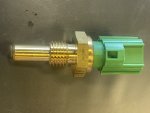
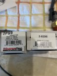
The decision was then made to replace the Coolant Temp Sensor with OTS modern day Temp Sensor from O'Reilly


IMG_4979.jpeg


IMG_4981.jpeg

the second pin will be connected to chassis GND

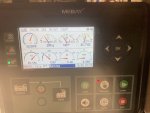
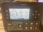
The gauges will show now this (simulated with equal resistances)


IMG_2331.jpeg

IMG_2315.jpeg

we will update the coolant temp sensor part number as soon as @Cowhunter sends me the info

to be continued….
 

peapvp

Well-known member
Steel Soldiers Supporter
1,159
1,344
113
Location
Basehor, KS
What are you using to actuate the throttle?
The throttle is the knob below cubicle, theses are the utility versions

We activate Fuel Shutoff Solenoid and Fuel Pumps with Output TB#4 (Fuel) and Crank / Start with Output TB #5 (Crank)
Output TB #6 (User Out 1) is the Field Flash and is activated by the MeBay DC-70DR MK II controller until Controller senses around 40 VAC on AC Inputs TB 27 (U) and TB 28 (V) - Controller is set to single phase 240 VAC

This was supposed to be my next post, once we get the MeBay DC-70DR MK II controller installed and the Genset running
 

Scoobyshep

Well-known member
1,307
1,970
113
Location
Florida
The throttle is the knob below cubicle, theses are the utility versions

We activate Fuel Shutoff Solenoid and Fuel Pumps with Output TB#4 (Fuel) and Crank / Start with Output TB #5 (Crank)
Output TB #6 (User Out 1) is the Field Flash and is activated by the MeBay DC-70DR MK II controller until Controller senses around 40 VAC on AC Inputs TB 27 (U) and TB 28 (V) - Controller is set to single phase 240 VAC

This was supposed to be my next post, once we get the MeBay DC-70DR MK II controller installed and the Genset running
Ah, I thought with the MPU you would have installed a servo to regulate the speed.

I did this with my 004, but due to a recent fire i have to do some repair work and was considering a control overhaul
 

peapvp

Well-known member
Steel Soldiers Supporter
1,159
1,344
113
Location
Basehor, KS
Ah, I thought with the MPU you would have installed a servo to regulate the speed.

I did this with my 004, but due to a recent fire i have to do some repair work and was considering a control overhaul
No, we use the mpu for crank disconnect in conjunction with oil pressure switch (not transducer). This will also start the field excitation at around 400 rpm if no AC voltage is present at the two AC terminals described above in post # 7
 

peapvp

Well-known member
Steel Soldiers Supporter
1,159
1,344
113
Location
Basehor, KS
@Scoobyshep the DC-70DR MK II controller supports CAN with various protocols for different engine ECU's through which one could operate a electronic Throttle / Governor. I have not tested this functionality yet, but it should be possible. The DC-70DR MK II controller does not have a analog output like the GAG Governor Controller and this would make a implementation of a CAN based ECU system necessary.
 

Guyfang

Moderator
Staff member
Moderator
17,491
25,872
113
Location
Burgkunstadt, Germany
Ah, I thought with the MPU you would have installed a servo to regulate the speed.

At first thought, that sounds like a good idea.

At second thought, Why? Keep it simple. So far everything I have seen sounds very good. After we converted all these precise and 400 hertz machines to MPU's and Electric governing systems, the MTBF increased vastly. At least 80%. But the majority of our problems were, Electric governors. Hands down. I have no doubt you have in todays tech, better electric governors. But again, I ask, why? Simple is good. Now if you are running a load the NEEDS PRECISE power, ok. fine. But a house or shop? Not even. We pulled our hair out over governors. The Electric Actuators? Bomb proof. The only problems with that is linkages. They require two swivel joints. If they were not every few months given a DROP of oil, they bound up. (Peter, there is a PS article about this!!) That was it for problems.
 

Scoobyshep

Well-known member
1,307
1,970
113
Location
Florida
Ah, I thought with the MPU you would have installed a servo to regulate the speed.

At first thought, that sounds like a good idea.

At second thought, Why? Keep it simple. So far everything I have seen sounds very good. After we converted all these precise and 400 hertz machines to MPU's and Electric governing systems, the MTBF increased vastly. At least 80%. But the majority of our problems were, Electric governors. Hands down. I have no doubt you have in todays tech, better electric governors. But again, I ask, why? Simple is good. Now if you are running a load the NEEDS PRECISE power, ok. fine. But a house or shop? Not even. We pulled our hair out over governors. The Electric Actuators? Bomb proof. The only problems with that is linkages. They require two swivel joints. If they were not every few months given a DROP of oil, they bound up. (Peter, there is a PS article about this!!) That was it for problems.
KISS UCIRRC
Keep It Simple Stupid. Unless Complex Is Really Really Cool.

Me personally, I added a servo to a 004, I use a PLC to read frequency and adjust as needed. In my defense I was left unsupervised
 

peapvp

Well-known member
Steel Soldiers Supporter
1,159
1,344
113
Location
Basehor, KS
KISS UCIRRC
Keep It Simple Stupid. Unless Complex Is Really Really Cool.

Me personally, I added a servo to a 004, I use a PLC to read frequency and adjust as needed. In my defense I was left unsupervised
Yes, that’s what they told me when they warned me, leave that @Scoobyshep alone unsupervised for one minute and all hell is going to break loose they said…….
 

peapvp

Well-known member
Steel Soldiers Supporter
1,159
1,344
113
Location
Basehor, KS
Latest Update:

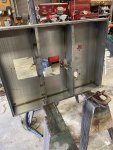
In the process of converting Larry’s 005A over to MeBay controller, we ran into the issues of a leaking fuel tank.
Same issue as always, pinholes in bottom of Tank.
Larry took his tank out and removed the bottom out, cleaned everything up and is getting ready to weld a new bottom back in.
Brass tubes will be thoroughly cleaned before welding the bottom back.

IMG_2939.png

76075049080__B3F901D8-44D7-40D0-9D9D-615D2E648E03.jpeg
 

Scoobyshep

Well-known member
1,307
1,970
113
Location
Florida
We are moving on in our project and would like to update the interested reader.

The MeBay DC-70DR MK II controller has reconfigurable Analog Inputs for

Coolant Temp Sneor [AUX S1 TB# 17]
Oil Pressure Senosr [AUX S2 TB# 18]

AUX S3 TB# 19 and AUX S4 TB# E1 and can be assigned through the software via a USB Cable and a Laptop

We assigned AUX S3 TB#19 to the Fuel Level Gauge

The Analog Inputs can be scaled to fit the resistance vs the gauge level in up to 10 Increments

However, the maximum Resistance is limited to 999 Ohms

For the existing fuel level sending you unit ( 0 Ohms Empty to ~ 30 Ohms full) and the Oil Pressure Transducer (0 Ohm 0 PSI to ~ 24 Ohm 60 PSI)

This poses no problem and we can use the existing Transducers

However, the Coolant Temp Sensor does not drop below 1 KOhm until it reaches well over 200 F
We measured 1.013 KOhm @ 180F

The decision was then made to replace the Coolant Temp Sensor with OTS modern day Temp Sensor from O'Reilly


View attachment 938744


View attachment 938745

the second pin will be connected to chassis GND

The gauges will show now this (simulated with equal resistances)


View attachment 938746

View attachment 938747

we will update the coolant temp sensor part number as soon as @Cowhunter sends me the info

to be continued….
I am having some difficulty finding the software for these. By chance do you have a link?
 

peapvp

Well-known member
Steel Soldiers Supporter
1,159
1,344
113
Location
Basehor, KS
I am having some difficulty finding the software for these. By chance do you have a link?
we downloaded the software package as zip file from MeBay.cn in the end of December last year.
We installed the software on a standalone Laptop without internet or better any network connection at all out of safety concerns

The software was checked with three different antivirus and anti malware programs and passed all three as clean.

However, due to the political situation for the last few years we would only recommend the installation on a PC with absolutely no network connectivity, not even Bluetooth

this download link is from one of our Dropbox accounts and contains the checked software package in zip file format

Disclaimer:
Use at your own Risk! We do not accept any liability in the case of failure or damage to your PC and or Generator

MeBay Software Package
 
Last edited:

peapvp

Well-known member
Steel Soldiers Supporter
1,159
1,344
113
Location
Basehor, KS
Update:

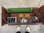
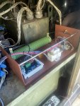
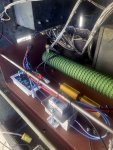
Larry built the "new" A11 based on the AVDR 054 with the additional Resistors and Relay based on the suggested wiring diagram in this post:

Mep004 circuit to replace faulty voltage regulator. This was designed by member peapvp

Please note:

Larry built the new A11 prior to updating the cubicle with the MeBay Controller.
Therefore, The Push Button and the new 1 K Ohm Voltage Regulator Potentiometer wires were routed temporarily around the cubicle.
This will be cleaned up during the install of the MeBay Controller.

The Push Button Switch for excitation will also be eliminated as the MeBay controller will do the excitation on Output #6, which will start around 600 RPM and stop when MeBay senses Generator AC Voltage. In other words the MeBay controller will do the excitation automatically.

If I understand the MeBay Manual correctly, then output #6 is only activated if the MeBay Controller has not sensed any AC Voltage at 600rpm due to self excitation by means of the presence of residual magnetism in exciter coil.

At the first test run, we found out that Larry's 005A had still enough residual magnetism left in his exciter coil from a previous run with the old A11 a few days prior for several hours.

We tested the Push Button Excitation anyway and the DC Voltage on TB16 F1 and F2 is app 9 VDC

Then Larry adjusted the Trim Pots VOLT and STAB on the 054. We found out that the two outer wires on the Voltage Potentiometer were backwards and the Pot would increase Voltage in counter clockwise direction. Larry swapped the two wires and then everything was back on track.

Next was the STAB adjustment. You wil need a analog meter to do this adjustment. We found a Gardner Bender 19-Range Analog Meter GMT-319 on the Home Depot Website (online only) and Amazon

The analog meter was set to 50 VDC Range. Larry turned the Trim Pot STAB as indicated clockwise until needle acted erratic (around 10V DC) and then he turned the Trim Pot counter clockwise until needle on meter was stable, which is 7 VDC with no load on Genset.

After that, Larry did a load test for 1 hour which worked fine

Load was set to 55% since we switched back to 3 Phase 208V/120V and had attached only a single phase load

I assisted Larry during some parts of the install via Facetime

This was Larry's ( @Cowhunter ) first time he built a electrical aparatus and I would say, he did a outstanding job! A+ for sure!

to be continued.....

001.jpg

image0.jpeg

image1.jpeg

image2.jpeg

image3.jpeg

image4.jpeg

Video:
MEP 005A with ADVR 054 Voltage Regulator
 
Top