• Steel Soldiers now has a few new forums, read more about it at: New Munitions Forums!

  • Microsoft MSN, Live, Hotmail, Outlook email users may not be receiving emails. We are working to resolve this issue. Please add support@steelsoldiers.com to your trusted contacts.

CUCV alternator symptoms, diagnosis and fix.

Status
Not open for further replies.
The voltmeter on the CUCV is actually a 12v version. There is a 300ohm resistor added to the back on the meter to make it work as a 24v unit. This resistor is the white flat ceramic unit. I don't know if anyone ever found a replacement, but many members has built their own with Radio Shack resistors. Been document many times.
6 - clear as mud?
Yep - and good to know. My point was not with bulbs so much as the potential confusion with including only the gen 2 bulb circuit - and only half of that, on E/F-4
 

Warthog

Moderator
Super Moderator
Steel Soldiers Supporter
13,774
232
63
Location
OKC, OK
My point was not with bulbs so much as the potential confusion with including only the gen 2 bulb circuit - and only half of that, on E/F-4
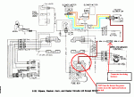
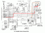
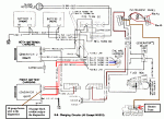
They couldn't put everything on each diagram. Diagram E/F-9 has the complete circuit for GEN2 and most of GEN1. Sometimes you have to look at many diagrams to "see" everything. :wink:

Yep you have found one of the flaws in the diagrams.

The complete circuit for GEN1 is not shown on any diagram.

If you look at the E/F-4 diagram you will see the "Heater blower" fuse is controled by the ignition switch. It feeds the right side of the heater fuse via the orange wire.

diagram E/F-20 shows the path of the heater coming out of the left side of the fuse via a brown wire 50A.

Diagram E/F-9 shows part of the GEN1 circuit. I have added some info to that diagram

What is NOT shown anywhere is the second brown wire also attached to the left side of the fuse. It is also brown and goes to pin #5 of the instrument cluster. Pin #5 supplies power to the GEN1 bulb circuit, the 4x4 indiator light and the Low Oil idiot light. If you trace a physical instrument cluster circuit board you can see that.

So the circuit for GEN1 is :

1 - Battery to 12v Terminal block on the firewall
2 - 12v Termninal Block to the Ignition switch (goes thru the firewall)
3 - Ignition switch to the Heater fuse
4 - Heater fuse to the instrument cluster connector #5
5 - Connector #5 to the GEN1 bulb
6 - GEN1 bulb to cluster connector #8
7 - Cluster connector #8 to the firewall plug
8 - firewall plug to GEN1 pin #1
 

Attachments

Last edited:

Durango_USMC

Member
663
0
18
Location
Indianapolis, IN
The red plastic piece needs to be replaced. Only way to do that is to take the alternator apart. Might as well rebuild it while it is apart (unless you have done it recently).
Thanks. Back to square 1.2 I guess. I'm not sure when the last time it was rebuilt was I know I havent rebuilt it in the 4 months I've owned it. I'm looking at this kit for the rebuild.

http://www.aspwholesale.com/index.php?act=viewProd&productId=5137

I just need to find that insulated plastic piece to keep it from shorting out and sparks flying etc. This truck is really becoming a love/hate thing.
 

Warthog

Moderator
Super Moderator
Steel Soldiers Supporter
13,774
232
63
Location
OKC, OK
Last edited:

Keith_J

Well-known member
3,657
1,323
113
Location
Schertz TX
I found an interesting cause to a GEN2 light not illuminating with key on, engine off situation. It was a dirty relay which switches the back battery to the alternator's brown wire (voltage sense). These are the Bosch brand relays under the dash. The truck had been refinished sometime in the 1990s with the CARC removed with plastic blasting media, some of this had seeped into the otherwise sealed relay.

I ran through all the no-light checks until finding this cause. It is the same type of relay as the voltmeter's so you could swap to check if the voltmeter is working. Being a budget build, I cut the relay open and cleaned the contacts. Then glued it back together when it worked on the bench.
 

fuzzpuss

Member
71
2
8
Location
Pahrump,NV
Ok I posted somewhere else about my 09 electrical woes but here goes: ok, had a grounded starter cable it caused all kinds of ****. Needless to say, I fixed most of the fried ground wires I could see or know about including the drivers side alt replacement. I got it running but its not charging, I have 25 volts to both alternators at the red wire with key off. Where is the step down in voltage occur at? I also have no headlights and 25 volts there too. So what am I missing here? I tested all the things that I was advised to do, but I cant seem to find out where the step down in voltage occurs at.
 
Last edited:

Barrman

Well-known member
5,266
1,782
113
Location
Giddings, Texas
There isn't a step down. If you put your volt meter negative lead on the front battery negative terminal and positive lead on the front battery positive terminal, you will get 12-14.4 volts. If you put your volt meter negative on the rear battery negative terminal and the positive lead on the back battery positive terminal, you will get 12-14.4 volts. Assuming you have good batteries and working alternators.

12 volts for the vehicle system is pulled from the negative terminal of the rear battery and sent to the engine wiring harness bus. That bus is on the drivers side firewall near the glow plug relay. Check what voltage you have there against any metal surface on the truck. It should be the same as the front battery. If not, you have some wires hooked up wrong.
 

cpf240

Active member
1,479
5
38
Location
Free in Northern Idaho
12 volts for the vehicle system is pulled from the negative terminal of the rear battery and sent to the engine wiring harness bus.
I keep seeing variations of this statement here, and I think it leads to some confusion.

While technically correct, one should consider that in the CUCV battery cable wiring scheme, the negative terminal of the rear battery and the positive terminal of the front battery are connected by the dog bone cable. This makes them, from an electrical point of view, the same thing. Sure, there is probably some teeny tiny resistance in the dog bone, but unless the dog bone is corroded, it is not enough to make a difference.

The fact that the wire that runs to the vehicles positive 12v buss over by the brake master cylinder comes off the clamp that is attached to the negative terminal of the rear battery is irrelevant. It would work the same if that cable was attached to the other end of the dog bone, on the clamp for the positive terminal of the front battery.

So, from that perspective, the 12v portion of the system is no different than any other negative-ground 12v vehicle system.

In my opinion. Your mileage may vary.
 

Barrman

Well-known member
5,266
1,782
113
Location
Giddings, Texas
I completely agree. It makes no difference. I wired my M715 up exactly like a CUCV when I put the 6.2 in it a few months ago. I had the 12V power pulled from the positive of the front battery. However, while my students were looking at the wiring diagram, they kept telling me I had it wrong. I flipped the dog bone over and even though it worked exactly the same. It now matched the wiring schematic and was therefore, "right." The question I was answering was asked by a guy that has wiring issues. I wanted to be specific about the way I phrased things so confusion would not be added.
 

cpf240

Active member
1,479
5
38
Location
Free in Northern Idaho
Well new alternator solved the Gen 2 light issue but voltmeter still says no charging or its inoperable..
Disconnect batteries, remove and disconnect voltmeter, connect it directly to a power source, such as the batteries and verify if the gauge works. If it does, then start tracing the wiring to the gauge. Remember that the gauge is *supposed* to have 24v at *ALL* times, but the ground connection for the gauge is switched through the voltmeter relay. Be very careful to not let the voltmeter wires short against anything!
 

Warthog

Moderator
Super Moderator
Steel Soldiers Supporter
13,774
232
63
Location
OKC, OK
Also the resistor on your voltmeter could be fried. Without it , no workie.
 

Warthog

Moderator
Super Moderator
Steel Soldiers Supporter
13,774
232
63
Location
OKC, OK
12 volts for the vehicle system is pulled from the negative terminal of the rear battery and sent to the engine wiring harness bus.
As it has been said, makes no difference as to which terminal the 12v power is taken from.

My "theory" as to the way GM wired it is this:

To make the system 24v, GM added the "dogbone" between the batteries. That cost XX number of pennies. The truck still needed 12v so they had to draw power from the front battery. Logic would tell you to run your 12v wire from the positive terminal of the front battery. BUT GM likes to save money. They already had ~15" of wire running to the rear battery and they need ~5' more to get to the 12v terminal, SO why not just tap into the rear battery and save ~15" of additional wire.

15" of wire on 100,000s of cables adds up. And you know how bean counters are.

Thats my theory and I'm sticking too it. Yea, thats the ticket. And I did stay at a Holiday Inn Express a few years ago.... :mrgreen:

P.S. When it comes time to replace your battery cables with new wire, many guys have moved the wire to the front battery
 
Last edited:

fuzzpuss

Member
71
2
8
Location
Pahrump,NV
"The fact that the wire that runs to the vehicles positive 12v buss over by the brake master cylinder comes off the clamp that is attached to the negative terminal of the rear battery is irrelevant."


Do you mean the passenger side of the engine compartment? This is an M1009 not an M1031.

I also checked and was getting resistance from the positive buss bar to the negative buss bar set on higher settings, but on lower settings it says nothing on the multimeter ;example setting 20k=0, 200=0, 2000=0, 200k =46, 2000k=406
I isn't no ilectrishun but should i be getting resistance at all?

P.S. my meter is digital so no little arm thingy.
 
Last edited:

cpf240

Active member
1,479
5
38
Location
Free in Northern Idaho
"The fact that the wire that runs to the vehicles positive 12v buss over by the brake master cylinder comes off the clamp that is attached to the negative terminal of the rear battery is irrelevant."


Do you mean the passenger side of the engine compartment? This is an M1009 not an M1031.

I also checked and was getting resistance from the positive buss bar to the negative buss bar set on higher settings, but on lower settings it says nothing on the multimeter ;example setting 20k=0, 200=0, 2000=0, 200k =46, 2000k=406
I isn't no ilectrishun but should i be getting resistance at all?

P.S. my meter is digital so no little arm thingy.
No, the buss on the passenger side is the 24v bus, and I was referring to the 12v buss.

As for the measurement you are getting between, what I assume is the 24v buss terminals, there is and/or was a noise filter capacitor tied between the + and - side of the 24v buss. Also, there could be a current path through other components connected to the 24v buss bars.
 

fuzzpuss

Member
71
2
8
Location
Pahrump,NV
I got ya on the buss bars... I am talking about the 24 volt positive and the negative under it. I checked the buss bar but I cant see anywhere it would be contacting anything that could do that... the noise filter do you know where I could get one for cheap? I found a company that sells one but I just about had a heart attack for the price quote... $257.00 for one.... Holy Smoke!!
 

doghead

4 Star General /Moderator
Staff member
Super Moderator
Steel Soldiers Supporter
26,246
1,179
113
Location
NY
You do not need the filter.
 

MarcusOReallyus

Well-known member
4,524
816
113
Location
Virginia
I got ya on the buss bars... I am talking about the 24 volt positive and the negative under it. I checked the buss bar but I cant see anywhere it would be contacting anything that could do that...

Make sure you have batteries disconnected while trying to measure resistance between those buss bars. If there are jolts there you'll get bogus readings. You should see infinite resistance, i.e., open circuit.
 

Cucvnut

Well-known member
3,804
61
48
Location
Carver, Oregon
So I have 14 volt while truck is running per alt, but my gauge shows almost in red, I just swapped a bad alt (Gen 1)that was Flickering while I drove, how do I tell if the charging system is correct and the gauge is bad? I know my front battery might not have been at full charge because of driving with the flickering gen 1 yesterday. I drove the truck and I had no more Flickering gen 1, so if it's putting out 29 volts while I m driving how do I repair the gauge?
 
Last edited:

fuzzpuss

Member
71
2
8
Location
Pahrump,NV
Thank everyone for all the replies. So far, I have checked every fusible link outside of the wire loom, both sides of each one show they have infinity.... good, I replaced the horn relay, have no idea where to get the diode but the napa guy said the new relay has it built in, it shows one as a diagram on the relay, (nice!). I replaced the big azz ugly 24 to 12 volt resistor on the firewall with a straight thru 12 volt primary wire from the front battery to the glow plug relay. I am also wondering if the volt gauge has gone bad. And now its so flippin hot here that I get about 2hrs. max to work on it nite and day, not to mention all the black widow spiders that blew in from riding on the wind.
 
Status
Not open for further replies.
Top
AdBlock Detected

We get it, advertisements are annoying!

Sure, ad-blocking software does a great job at blocking ads, but it also blocks useful features of our website like our supporting vendors. Their ads help keep Steel Soldiers going. Please consider disabling your ad blockers for the site. Thanks!

I've Disabled AdBlock
No Thanks