glimmertwin01
New member
- 30
- 0
- 0
- Location
- Rochester NY
Hey Guys especially you electrical gurus. Here is a new one for you! to start off YES, I have read the sticky, yes i have read and studied the TM and trouble shooting... which under 5.1 basically says trace all circuits.
History... Bought the truck and GEN2 light meter did not work. Removed and had Pass side Gen2 alternator rebuilt... still no light...
BACKGROUND
other issues that were fixed... the truck had a fragged flex plate due to a loose Un braced starter Had starter shaft replaced, and replaced flex plate.... all components installed properly...
A previous Genius (owner) had Cobbed in a push button starter. with single strand 12 ga. romex from the 24 v buss into dash to button and back out directly to starter solenoid. the wire was ugly....
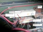
diagnosed that the under dash relay was not passing 24v. only about 12. on the purple trigger wire for the solenoid. My solution was similar to the doghead bypass. My version is... 24 V solenoid on firewall next to 24v buss and fuel filter assembly. 24v lead to one terminal, 12 Ga. lead from other to starter solenoid. purple wire to trigger, other leg to ground buss. result the trucks starts with key as it should.
All of this is mentioned as background "Just in case"
also replaced both relays in Gen 2 circuit.
(all other "idiot" lights (except Gen 2 lamp) in IP work and function)
this is where it gets good....
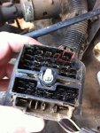
Here is the symptoms..... even after the above... No Gen 2 light... no Voltmeter. unplugged the plug on Gen 2 red wire +/- 24v key off, Brown/white wire key on less than 3v. the same low voltage is present throughout the entire circuit.
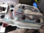
Removed instrument panel light and circuits... good
Removed and tested Gen2 Diode... good.
continuity tests... (good meaning passed continuity tests)
1) Gen2 plug on harness to firewall pass thru (junction block) Engine side... good
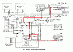
2) corresponding pin on female side of junction block pass thru to plug above the 10amp fuse as shown labeled as V/MTR (as shown on schematic) Good
3) fuse panel (in number 2 above) TO CORRESPONDING terminal on harness to Inst. panel plug...good
4) no broken damaged or cut wires found....
I just tried back feeding 24V GEN2 interior circuit with a lead directly from the 24V buss to the fuse panel V/MTR plug.... still no GEN2 LIGHT or Voltage at voltmeter ( voltmeter was replaced with a good 30v DC meter. )
should I try and locate a known working replacement interior wiring harness?? that is about where I am at....
HELP!!!!!!!!!!!


