• Steel Soldiers now has a few new forums, read more about it at: New Munitions Forums!

  • Microsoft MSN, Live, Hotmail, Outlook email users may not be receiving emails. We are working to resolve this issue. Please add support@steelsoldiers.com to your trusted contacts.

Diagnosing CTIS M1078

Lugnuts

Active member
Steel Soldiers Supporter
319
236
43
Location
Myakka City, FL
Yes, I have downloaded the Tech Manual and thank you for sharing that. My question and I haven't found it in the site is that pertaining to Software for Computer diagnostics of the system. Is it obtainable? And where might it be located? And has any person on this site done it and know it? I have 5 blinking lights and that lists a great amount of codes. Not insurmountable but perhaps looking to be more specific.
Your assistance would be greatly appreciated!!
Lugnuts
 

Ronmar

Well-known member
3,827
7,431
113
Location
Port angeles wa
Yes, I have downloaded the Tech Manual and thank you for sharing that. My question and I haven't found it in the site is that pertaining to Software for Computer diagnostics of the system. Is it obtainable? And where might it be located? And has any person on this site done it and know it? I have 5 blinking lights and that lists a great amount of codes. Not insurmountable but perhaps looking to be more specific.
Your assistance would be greatly appreciated!!
Lugnuts
I don’t think accessing the CTIS controller with software is going to narrow down the trouble code any, as the system only has one sensor And a supply tank pressure switch to report air supply status... 5 flash means the controller did not see something within a set time, or it preformed a sequence and did not see an expected result(expected stable pressure). 5flash is almost always caused by an air leak, but that can be determined by what actions the controller took before it went to the 5flash fault.

here is the basic sequence of operation:
You start the engine and the compressor starts filling the tanks, once the CTIS wet tank switch closes(117 PSI) the processor closes the control solenoid vlve on the PCU to seal the system. Then the controller briefly opens the PCU supply solenoid valve and gives a shot of air to pressurize the system. Pressure in the system over about 6-7 PSI opens the wheel valves and the system pressure will stabilize at the tire pressure.

The controller then reads the pressure sensor on the PCU. It is looking at pressure and that it is NOT changing, which would indicate a leak or a large tire imbalance. IF IT DOES NOT SEE A STABLE PRESSURE IT WILL FAULT, to tell the operator to fix the system... If it has a steady pressure it compares that with the programmed pressure for the selected mode. If it is high or low it will deflate or inflate as needed and the selected mode light will flash indicating it is working on reaching that mode. As it does so it will check the pressure change at intervals till it reaches its programmed pressure. If it is deflating or inflating and it doesn’t see an expected change at one of its checks(bad sensor), it will fault.

when it has reached it’s comanded pressure, it will open the control solenoid, vent the system which closes all the wheel valves, and it gives you a steady mode lite for the selected mode. It will repeat this process every 15 minutes and adjust(or fault) as necessary.

Basically you are riding on some air filled bombs. For safety, the pea brain in the controller with one sensor and a pressure switch will fault at the drop of a hat unless it is absolutely sure it has complete control of the process...

With a little observation you can determine what actions the controller has taken before it faulted which will help you find the issue. This is easier to observe if you remove the passenger kick panel to get to the PCU manifold.

if you start the truck and nothing happens then after a while the unit shifts to 5flash, your air system isn’t going over 117 PSI in the wet tank or the wet tank switch is bad.

When the supply switch closes at 117 PSI you should be able to hear the processor close the control solenoid and give a shot of air at the PCU. If it faults after that, it probably measured unstable air pressure so you have a leak or the tires are at different pressures and their trying to equalize causes an unstable pressure reading. Yes, it will fault if the tire pressures are not the same...

so what is yours doing?
 

Lugnuts

Active member
Steel Soldiers Supporter
319
236
43
Location
Myakka City, FL
I don’t think accessing the CTIS controller with software is going to narrow down the trouble code any, as the system only has one sensor And a supply tank pressure switch to report air supply status... 5 flash means the controller did not see something within a set time, or it preformed a sequence and did not see an expected result(expected stable pressure). 5flash is almost always caused by an air leak, but that can be determined by what actions the controller took before it went to the 5flash fault.

here is the basic sequence of operation:
You start the engine and the compressor starts filling the tanks, once the CTIS wet tank switch closes(117 PSI) the processor closes the control solenoid vlve on the PCU to seal the system. Then the controller briefly opens the PCU supply solenoid valve and gives a shot of air to pressurize the system. Pressure in the system over about 6-7 PSI opens the wheel valves and the system pressure will stabilize at the tire pressure.

The controller then reads the pressure sensor on the PCU. It is looking at pressure and that it is NOT changing, which would indicate a leak or a large tire imbalance. IF IT DOES NOT SEE A STABLE PRESSURE IT WILL FAULT, to tell the operator to fix the system... If it has a steady pressure it compares that with the programmed pressure for the selected mode. If it is high or low it will deflate or inflate as needed and the selected mode light will flash indicating it is working on reaching that mode. As it does so it will check the pressure change at intervals till it reaches its programmed pressure. If it is deflating or inflating and it doesn’t see an expected change at one of its checks(bad sensor), it will fault.

when it has reached it’s comanded pressure, it will open the control solenoid, vent the system which closes all the wheel valves, and it gives you a steady mode lite for the selected mode. It will repeat this process every 15 minutes and adjust(or fault) as necessary.

Basically you are riding on some air filled bombs. For safety, the pea brain in the controller with one sensor and a pressure switch will fault at the drop of a hat unless it is absolutely sure it has complete control of the process...

With a little observation you can determine what actions the controller has taken before it faulted which will help you find the issue. This is easier to observe if you remove the passenger kick panel to get to the PCU manifold.

if you start the truck and nothing happens then after a while the unit shifts to 5flash, your air system isn’t going over 117 PSI in the wet tank or the wet tank switch is bad.

When the supply switch closes at 117 PSI you should be able to hear the processor close the control solenoid and give a shot of air at the PCU. If it faults after that, it probably measured unstable air pressure so you have a leak or the tires are at different pressures and their trying to equalize causes an unstable pressure reading. Yes, it will fault if the tire pressures are not the same...

so what is yours doing?
Ronmar
Thank you for the skinny on the unit. I think you have given me a place to really start diagnostics.
I know that I have bad valves at the wheels, the ones right before the Schrader Valves. My tires are pretty much flat and when inflated to correct pressures it is 3 days and they are flat again. I have in the past pulled those valves apart and the aluminum corrosion is significant enough to not let the diaphragm seat.
When started the air pressure builds to air dryer exhaust in 2 to 2:30 minutes. The CTIS does its initial discharge and then it is after that the lights start flashing. I have not determined exactly when but if I repost the Highway Button it will again try inflation. If I keep pushing the button they will slowly inflate the tires after about a half an hour.
Some of the nomenclature I would like to clarify.
The PCU? Pressure Control Unit? Location?
What is a stable pressure that it is looking for?
Control Solenoid location?
The PCU control solenoid ? Am I looking to tap into that with a gauge to monitor Pressure?

Thank you for you assistance! And thank you for the overview.
 

Ronmar

Well-known member
3,827
7,431
113
Location
Port angeles wa
Ronmar
Thank you for the skinny on the unit. I think you have given me a place to really start diagnostics.
I know that I have bad valves at the wheels, the ones right before the Schrader Valves. My tires are pretty much flat and when inflated to correct pressures it is 3 days and they are flat again. I have in the past pulled those valves apart and the aluminum corrosion is significant enough to not let the diaphragm seat.
When started the air pressure builds to air dryer exhaust in 2 to 2:30 minutes. The CTIS does its initial discharge and then it is after that the lights start flashing. I have not determined exactly when but if I repost the Highway Button it will again try inflation. If I keep pushing the button they will slowly inflate the tires after about a half an hour.
Some of the nomenclature I would like to clarify.
The PCU? Pressure Control Unit? Location?
What is a stable pressure that it is looking for?
Control Solenoid location?
The PCU control solenoid ? Am I looking to tap into that with a gauge to monitor Pressure?

Thank you for you assistance! And thank you for the overview.
The pressure control unit is the manifold that the controller manipulates to control the system. It is located under the passenger dash, an aluminum block with hoses connected to it and a black plastic cover on the bottom. It has 3 solenoid valves under that plastic cover. One is the control solenoid, it is normally open to vent the manifold and the controller must energize it to close it and seal the system. It vents the manifold into that plastic cover which has a hose that connects it to a port on the floor to vent the air outside the cab.
The second valve is the supply valve. When the controller energizes it, it lets in supply air from the wet tank to pressurize the system/inflate the tires.
The third valve is the deflate valve. When energized it connects the manifold to a little 6.5PSI pressure relief valve on the side of the manifold block. This vents the system down to that point, which is just enough to keep the wheel valves open. Since the pressure in the tires is greater, air trys to flow back from the tires to the manifold. This reversal in flow causes the dump valves(remote pressure regulators) to vent the tire air rapidly.

The stable pressure it is looking for is the combined tire and system pressure. When the system is sealed and the wheel valves are open the tires should all equalize at the same pressure. If one or two tires are at a different pressure this can take a while to equalize thru the plumbing and the controller may fault Because the pressure is changing.

The only place to really sample the manifold pressure, already has the pressure transducer installed there. You can monitor the pressure at the tire Schrader valves... if you can get it to fill then it was probably faulting because not all the tire pressures were the same initially and it takes a while to equalize them. If low, 30 minutes to fill at idle sounds about right, they take a huge ammount of air. When low, the tires will empty a 120 PSI wet tank down to its 85psi cutoff in 3 seconds...

Finding leaks is a problem on the system as it only pressurizes in pulses and the engine is running. The easiest way is to disconnect the controller connector and jumper 28v to the control solenoid and momentarily jumper 28v to the supply solenoid to pressurize the system(as long as the wet tank is full). the system should then set at tire pressure as long as the control solenoid remains energized and you can look for leaks without the engine running...

my controller was bricked when I got my truck and I decided to go to manual control. Here is a video of how the PCU operates with me controlling the solenoids manually. The gauge on mine is connected where the pressure transducer was connected on the PCU...

 
Last edited:

Lugnuts

Active member
Steel Soldiers Supporter
319
236
43
Location
Myakka City, FL
The pressure control unit is the manifold that the controller manipulates to control the system. It is located under the passenger dash, an aluminum block with hoses connected to it and a black plastic cover on the bottom. It has 3 solenoid valves under that plastic cover. One is the control solenoid, it is normally open to vent the manifold and the controller must energize it to close it and seal the system. It vents the manifold into that plastic cover which has a hose that connects it to a port on the floor to vent the air outside the cab.
The second valve is the supply valve. When the controller energizes it, it lets in supply air from the wet tank to pressurize the system/inflate the tires.
The third valve is the deflate valve. When energized it connects the manifold to a little 6.5PSI pressure relief valve on the side of the manifold block. This vents the system down to that point, which is just enough to keep the wheel valves open. Since the pressure in the tires is greater, air trys to flow back from the tires to the manifold. This reversal in flow causes the dump valves(remote pressure regulators) to vent the tire air rapidly.

The stable pressure it is looking for is the combined tire and system pressure. When the system is sealed and the wheel valves are open the tires should all equalize at the same pressure. If one or two tires are at a different pressure this can take a while to equalize thru the plumbing and the controller may fault Because the pressure is changing.

The only place to really sample the manifold pressure, already has the pressure transducer installed there. You can monitor the pressure at the tire Schrader valves... if you can get it to fill then it was probably faulting because not all the tire pressures were the same initially and it takes a while to equalize them. If low, 30 minutes to fill at idle sounds about right, they take a huge ammount of air. When low, the tires will empty a 120 PSI wet tank down to its 85psi cutoff in 3 seconds...

Finding leaks is a problem on the system as it only pressurizes in pulses and the engine is running. The easiest way is to disconnect the controller connector and jumper 28v to the control solenoid and momentarily jumper 28v to the supply solenoid to pressurize the system(as long as the wet tank is full). the system should then set at tire pressure as long as the control solenoid remains energized and you can look for leaks without the engine running...

my controller was bricked when I got my truck and I decided to go to manual control. Here is a video of how the PCU operates with me controlling the solenoids manually. The gauge on mine is connected where the pressure transducer was connected on the PCU...

Thanks again. I will let you know how this turns out or diagnoses anyway. Most likely I'll have more questions
Have a great week end.
Lugnuts
 

Lugnuts

Active member
Steel Soldiers Supporter
319
236
43
Location
Myakka City, FL
Looking again for the assistance and guidance of Ronmar

Sir, here is where I am.
The first thing I proceeded with was to clean my wheel valves and as figured they were very crusty. I removed the supply air line from the wheel, cleaned the valve, and then filled the tire with air to 65 psi, and checked for leakage from the valve through the hose. No air leakage. So I will let that sit for a week and see if my tires and valve in fact hold air.
I then proceeded to the air tanks and removed the one valve that is on the tank to test to see if it closes and opens and corrects pressures.
It did. I then checked to see if there was a hot leg in the wiring and I found that there was. I do not have a wiring diagram of the system but after viewing the Pressure Control Unit on the passenger side kick board I came up with an surmising that all inputs are given to the Controller which is the push button piece to the right of the drivers knee and executed to the PCU.
I am sending an attachment, a picture of what I presume is the PCU and have questions to verify what I think know.
Air Lines S, D, and C are what?
You had stated that all valve were under the plastic cover and this one has one external of the cover. What is that?
Now for me to go under the plastic cover I would have to pull that unit (and that is fine) but on the right side of the box is a 6 pin connector and is that where the valves get their power and grounds? If so do you happen to have a pin out of that connector or is it more beneficial to remove the cover and access them that way?
There is also a air line above that connector that I am inquiring about. What is it?

Now I come to the quick release valves and the tire valves? I understand how the tire can fill by increasing the pressure into wheel valve and overriding the spring and diaphragm but how in the world does it let air out??? Now I take it that the air supply is like brakes and supplies working air to the quick release valves while controlling air comes from the PCU?

Please know that you are under no obligation to answer but if you don't have time for this please say so.

I thank you greatly
Lugnuts
 

Attachments

Ronmar

Well-known member
3,827
7,431
113
Location
Port angeles wa
S is the air supply line in from the wet tank.

D is the deflate port you will see a little pressure relief valve in that port.

C connects down to the dump/quick release valves and wheel plumbing.

The control solenoid vents the manifold into that bottom plastic cover. The line connected to that cover just connects to a floor vent port to send the air outside the cab.

The small device with the electrical connector is the pressure sensor.

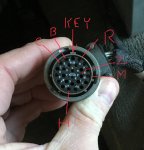
The other connector does connect to the 3 solenoid valves under the cover and its pinout is in the schematic found near the back of each tech manual. I find it easier to control the valves manually using the CTIS controller connector and a pair of jumpers as there is 24v in that connector already(see attached pic).

In the controller connector H is 24v When the main switch is on. Pin R feeds the control solenoid, B feeds the Supply solenoid and C feeds the deflate solenoid. Start the truck, fill the air tanks and shutdown. I take 2 jumper wires and twist one end of each together into a “V” Put the point of the V jumper wire in H. Turn on the main switch and Put the other end of one wire into R. You should hear the control solenoid close. Take the other jumper and briefly(1 second) place it into B. Y0u will hear the supply solenoid open and air flow. This will open all the wheel valves and the system should set at tire pressure as long as the H to R jumper supplies power to the control solenoid. Now leaks are easilly located without the engine running... with a full wet tank, you can do this at least 4 times before you have to recharge the airtanks...

Wheel valves: the tire line is connected to the tiny center port. The truck side line feeds the whole rest of the face of the diaphragm. On the other side of the diaphragm is a spring and atmospheric pressure. High tire air pressure on that center port cant make enough force to lift the diaphragm so the tire port stays closed. When you put only about 6 PSI on the truck side port it can push on the entire diaphragm face and pushes it open easilly, so any more than 6PSI on the truck side = open wheel valve.

Dump Valves: they are a remote pressure regulator. Whatever pressure you apply to the inlet, they try and maintain on the outlet, either by feeding air from inlet to outlet, or by feeding air back to inlet or dumping air from the outlet side to the vent till the outlet matches the inlet. Same type of valve is used on the brakes. Step on the pedal, air flows and brakes are applied, release the pedal and you hear air vented under the truck to quickly release the brake pressure at the wheels.

When you briefly apply air from supply(and the control/vent is closed) that pressure is copied by the dump valves and applied to the wheel valves. Over 6PSI the wheel valves open and everything stabilizes at the average wheel pressure. Or if you continue to supply air, it flows thru the dump valves and thru the wheel valves to flow into the tires...

Remember that little brass relief valve in the D port on the PCU? When you open the deflate solenoid, it connects the manifold to that port and that relief dumps everything above 6.5 PSI(acts like a regulator). That 6.5 PSI left in the manifold is then mimicked by the dump valves and applied to the wheels. Since it is more than 6PSI, the wheel valves stay open, but the tire pressure is far greater, so air flows out of the tires trying to fill that lower pressure line, but the dump valves have 6.5PSI on their input side so will dump any excess air provided by the tires to the vent, to match the 6.5 PSI on their inlet...

Removing the H-R jumper(or shutting off the main switch), opens the control solenoid and vents the PCU manifold to 0PSI. The dump valves copy this on their outlet side, and the wheel valves going below 6PSI close the tire ports...


4366E737-CEE5-4074-83C7-C15B60AEB54B.jpeg
 
Last edited:

Lugnuts

Active member
Steel Soldiers Supporter
319
236
43
Location
Myakka City, FL
S is the air supply line in from the wet tank.

D is the deflate port you will see a little pressure relief valve in that port.

C connects down to the dump/quick release valves and wheel plumbing.

The control solenoid vents the manifold into that bottom plastic cover. The line connected to that cover just connects to a floor vent port to send the air outside the cab.

The small device with the electrical connector is the pressure sensor.

The other connector does connect to the 3 solenoid valves under the cover and its pinout is in the schematic found near the back of each tech manual. I find it easier to control the valves manually using the CTIS controller connector and a pair of jumpers as there is 24v in that connector already(see attached pic).

In the controller connector H is 24v When the main switch is on. Pin R feeds the control solenoid, B feeds the Supply solenoid and C feeds the deflate solenoid. Start the truck, fill the air tanks and shutdown. I take 2 jumper wires and twist one end of each together into a “V” Put the point of the V jumper wire in H. Turn on the main switch and Put the other end of one wire into R. You should hear the control solenoid close. Take the other jumper and briefly(1 second) place it into B. Y0u will hear the supply solenoid open and air flow. This will open all the wheel valves and the system should set at tire pressure as long as the H to R jumper supplies power to the control solenoid. Now leaks are easilly located without the engine running... with a full wet tank, you can do this at least 4 times before you have to recharge the airtanks...

Wheel valves: the tire line is connected to the tiny center port. The truck side line feeds the whole rest of the face of the diaphragm. On the other side of the diaphragm is a spring and atmospheric pressure. High tire air pressure on that center port cant make enough force to lift the diaphragm so the tire port stays closed. When you put only about 6 PSI on the truck side port it can push on the entire diaphragm face and pushes it open easilly, so any more than 6PSI on the truck side = open wheel valve.

Dump Valves: they are a remote pressure regulator. Whatever pressure you apply to the inlet, they try and maintain on the outlet, either by feeding air from inlet to outlet, or by feeding air back to inlet or dumping air from the outlet side to the vent till the outlet matches the inlet. Same type of valve is used on the brakes. Step on the pedal, air flows and brakes are applied, release the pedal and you hear air vented under the truck to quickly release the brake pressure at the wheels.

When you briefly apply air from supply(and the control/vent is closed) that pressure is copied by the dump valves and applied to the wheel valves. Over 6PSI the wheel valves open and everything stabilizes at the average wheel pressure. Or if you continue to supply air, it flows thru the dump valves and thru the wheel valves to flow into the tires...

Remember that little brass relief valve in the D port on the PCU? When you open the deflate solenoid, it connects the manifold to that port and that relief dumps everything above 6.5 PSI(acts like a regulator). That 6.5 PSI left in the manifold is then mimicked by the dump valves and applied to the wheels. Since it is more than 6PSI, the wheel valves stay open, but the tire pressure is far greater, so air flows out of the tires trying to fill that lower pressure line, but the dump valves have 6.5PSI on their input side so will dump any excess air provided by the tires to the vent, to match the 6.5 PSI on their inlet...

Removing the H-R jumper(or shutting off the main switch), opens the control solenoid and vents the PCU manifold to 0PSI. The dump valves copy this on their outlet side, and the wheel valves going below 6PSI close the tire ports...


View attachment 820383
You the man!!! This is one of those posts that will be around to help others for a long time.
Thank you greatly and I'll let you know how this turns out.
I figure if I put charged air line from my shop compressor into one of the drains on the wet tank I should be able to work without noise and go uninterrupted in the execution of diagnostics. Merry Christmas. Lugnuts
 

Ronmar

Well-known member
3,827
7,431
113
Location
Port angeles wa
You the man!!! This is one of those posts that will be around to help others for a long time.
Thank you greatly and I'll let you know how this turns out.
I figure if I put charged air line from my shop compressor into one of the drains on the wet tank I should be able to work without noise and go uninterrupted in the execution of diagnostics. Merry Christmas. Lugnuts
you can connect your air compressor to the front red emergency gladhand. It will charge the whole air system thru that port. It also releases the park brake so chock the wheels:) you can unscrew the vent nipple off of a vented gladhand cover. It is national pipe thread port on the cover and can easily adapt it to a standard air hose fitting then replace the cover on the gladhand.
 

MrMikey4026

Well-known member
281
417
63
Location
Eatonville Washington
One of the best things I learned while working on my CTIS is that the controller is highly sensitive to system leaks on the controlled side .
The best way I found to find the leaks was to remove the line from the modulator valve assembly that goes to quick release valves that supplies air to the wheel ends of the system and connect a cylinder leakdown tester in place feeding the controlled side. Using a separate compressor works best, no noise that way (I used my shop air). You can dial the pressure up and test the entire system after the modulator with soap suds. You can operate the inflation system (after the modulator valve) with it, you can dial the pressure to whatever you like, both up and down. Raise the pressure, it inflates. Set the pressure to 20 PSI, the tires go to 20 PSI, set the pressure to 10 PSI and you have nearly flat tires.
I found intermittently leaking quick release valves and loose/leaking fittings.
I replaced the quick release valves with Bendix units for about 18$ each. There is no reason to buy the expensive original style.
I was tempted to operate the whole system permanently with the leakdown tester, until I found a working controller.
Just remember if you leave it permanently to turn it all the way down (release all the pressure) to vent the controlled side, or as tank pressure drops, all of your tires will air down also.
 

Lugnuts

Active member
Steel Soldiers Supporter
319
236
43
Location
Myakka City, FL
Thank you. Just two question, what are you calling the modulator valve and what is the location of said valve. Lugnuts
 

MrMikey4026

Well-known member
281
417
63
Location
Eatonville Washington
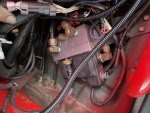
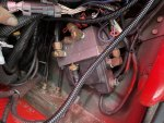
This is the modulator valve, (also called the valve manifold), I borrowed your picture. One line is supply air pressure from the wet air tank thru the pressure protection valve, one line is controlled air pressure to your quick release valves, one line is the vent.
I don't have a modulator valve in front of me, so I can't remember which air line is witch, but it will not be hard to figure out. I do know the one screwed into the black cover is the vent, make sure it is not plugged up with a bug nest!
I have no idea how I ended up with two of your pictures?
1607642328136.png1607642328136.png
 

Mullaney

Well-known member
Steel Soldiers Supporter
Supporting Vendor
7,711
19,750
113
Location
Charlotte NC
I don’t think accessing the CTIS controller with software is going to narrow down the trouble code any, as the system only has one sensor And a supply tank pressure switch to report air supply status... 5 flash means the controller did not see something within a set time, or it preformed a sequence and did not see an expected result(expected stable pressure). 5flash is almost always caused by an air leak, but that can be determined by what actions the controller took before it went to the 5flash fault.

here is the basic sequence of operation:
You start the engine and the compressor starts filling the tanks, once the CTIS wet tank switch closes(117 PSI) the processor closes the control solenoid vlve on the PCU to seal the system. Then the controller briefly opens the PCU supply solenoid valve and gives a shot of air to pressurize the system. Pressure in the system over about 6-7 PSI opens the wheel valves and the system pressure will stabilize at the tire pressure.

The controller then reads the pressure sensor on the PCU. It is looking at pressure and that it is NOT changing, which would indicate a leak or a large tire imbalance. IF IT DOES NOT SEE A STABLE PRESSURE IT WILL FAULT, to tell the operator to fix the system... If it has a steady pressure it compares that with the programmed pressure for the selected mode. If it is high or low it will deflate or inflate as needed and the selected mode light will flash indicating it is working on reaching that mode. As it does so it will check the pressure change at intervals till it reaches its programmed pressure. If it is deflating or inflating and it doesn’t see an expected change at one of its checks(bad sensor), it will fault.

when it has reached it’s comanded pressure, it will open the control solenoid, vent the system which closes all the wheel valves, and it gives you a steady mode lite for the selected mode. It will repeat this process every 15 minutes and adjust(or fault) as necessary.

Basically you are riding on some air filled bombs. For safety, the pea brain in the controller with one sensor and a pressure switch will fault at the drop of a hat unless it is absolutely sure it has complete control of the process...

With a little observation you can determine what actions the controller has taken before it faulted which will help you find the issue. This is easier to observe if you remove the passenger kick panel to get to the PCU manifold.

if you start the truck and nothing happens then after a while the unit shifts to 5flash, your air system isn’t going over 117 PSI in the wet tank or the wet tank switch is bad.

When the supply switch closes at 117 PSI you should be able to hear the processor close the control solenoid and give a shot of air at the PCU. If it faults after that, it probably measured unstable air pressure so you have a leak or the tires are at different pressures and their trying to equalize causes an unstable pressure reading. Yes, it will fault if the tire pressures are not the same...

so what is yours doing?

Hi Ronmar ,

I have a M1088 that seems to have one tire that either isn't getting air or CTIS just isn't feeding air to that one tire. Some time back, I posted a picture of a tire with a bolt in it. Got that solved with a plug. Should have been patched, but at the moment - it solved my problem. I know for sure that the CTIS was working then. I pulled the bolt out, let most of the air out of the tire, then "followed" the bolt with a tool so I wouldn't punch another hole in inside of the tire. Started the truck and CTIS aired that tire back up.

Shortly after that, my batteries were stolen and the truck sat for a while until I got smart enough to follow the wires and got some great advise here as well. All that is resolved now and I am really happy to have my toy in drive-able condition again!

I don't remember the CTIS controller blinking before except just after startup. Now it blinks all the time. I can't help but wonder if I shorted it when re-powering the truck - or if something is keeping that one wheel from getting air. I have sprayed soapy water on everything (including my plug) and nothing bubbles.

I saw in this post some mention of a filter in the lines to the wheels... I haven't cracked it open yet to see if that might be my problem. I guess before I hook it to shop air and jumper as you detailed above - I just have to ask - if maybe it being one tire with the problem points you to something specific? Maybe?
 

Ronmar

Well-known member
3,827
7,431
113
Location
Port angeles wa
Hi Ronmar ,

I have a M1088 that seems to have one tire that either isn't getting air or CTIS just isn't feeding air to that one tire. Some time back, I posted a picture of a tire with a bolt in it. Got that solved with a plug. Should have been patched, but at the moment - it solved my problem. I know for sure that the CTIS was working then. I pulled the bolt out, let most of the air out of the tire, then "followed" the bolt with a tool so I wouldn't punch another hole in inside of the tire. Started the truck and CTIS aired that tire back up.

Shortly after that, my batteries were stolen and the truck sat for a while until I got smart enough to follow the wires and got some great advise here as well. All that is resolved now and I am really happy to have my toy in drive-able condition again!

I don't remember the CTIS controller blinking before except just after startup. Now it blinks all the time. I can't help but wonder if I shorted it when re-powering the truck - or if something is keeping that one wheel from getting air. I have sprayed soapy water on everything (including my plug) and nothing bubbles.

I saw in this post some mention of a filter in the lines to the wheels... I haven't cracked it open yet to see if that might be my problem. I guess before I hook it to shop air and jumper as you detailed above - I just have to ask - if maybe it being one tire with the problem points you to something specific? Maybe?
The wheels all get fed air equally, so one tire not getting air indicates an issue with that one wheel alone. First check I would make is to insure the banjo bolt where the air line on the wheel connects to the hollow hub supply, is indeed a hollow banjo bolt with a cross hole. If a regular bolt gets installed there, there is no way for truck air to reach the wheel valve. Next would be an issue or obstruction in the wheel valve itself... they are easy enough to take apart and inspect, just put a jack stand under the axle, deflate the tire and remove the wheel valve cover.
 

Lugnuts

Active member
Steel Soldiers Supporter
319
236
43
Location
Myakka City, FL
Just catching up on what has evolved thus far:
First I filled the air tanks and found the air switch that signifies to the CTIS controller that air pressure has been obtained is working.
Secondly, I performed the test mentioned earlier in this article to see if my manifold was working and where the air leaks in the system were.
Thirdly, I heard solenoids working but no air pressure being dispersed.
Fourth, My supply side air was non existent at the PCU manifold and upon diagnostics found that my Wet Tank Valve that supplies air to the system is bad as in letting next to nothing in air by. For a note, also found that the air line first travels to the air over hydraulic cab lift and then to the CTIS manifold.
After gutting the valve and getting air supply to the manifold and proceeded to the prior test and found that front left hub seals were blown. After removing the air line at the hub and plugging I proceeded with more tests.
That was my only leak but I did come up with more questions which I am directing to Ronmar. When air was applied to the system the Quick Release Valves were barking as in an intermittent blast of air that I don't believe was ever making anything goes to the wheels. Doesn't seem normal to me so I am asking if the quick release valves are bad or ???
Last question. How does the flat tire function on the PCU work? As I understand if a tire is shot and leaking and you need to leave the scene you push that button and all air is directed to the leaking tire so that you can go, and with that the CTIS is not suppose to quit working and yet it has been stated that these units are sensitive to air leaks? It kind of goes with the above inquiry that if you have a flat and repair the hole why couldn't one go to flat mode to inflate the downed tire or if they are all unequally low without upsetting you CTIS?
Thank you
Lugnuts
 

Reworked LMTV

Expedition Campers Limited, LLC
Supporting Vendor
1,506
1,173
113
Location
TN
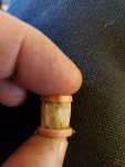
You mentioned the valves being cleaned. Did you check the filters ? They can become clogged with a waxy oil base substance from leaking hub CTIS seals. Tires won't be able to inflate and deflate as designed. These don't clean very well. Best to replace. Several sources on the well-known auction site.
 

Attachments

Last edited:

Ronmar

Well-known member
3,827
7,431
113
Location
Port angeles wa
You have followed the plumbing, left is “T” d to right and front is “T”d to rear. There is no way to send air to just one tire. In emergency mode, the timed routine is changed and the controller simply checks the tire pressure much more frequently and adds as necessary, instead of the normal 15 minute checks. It probably also overrides or loosens the parameters on the need for stable pressure at it’s pressure checks. One leaking tire will deflate on it’s own but as soon as the system is pressurized and all the wheel valves are open, 3 good tires will attempt to fill and equalize the leaking tire...

the quick release/dump valves don’t make much noise when air is applied to their supply. The only time they really make noise is when pressure is released from the supply side and they dump their output side to the vent to equal that low supply pressure. So every time the PCU opens the control solenoid and releases system pressure, they honk briefly.

Now if your supply was feeding slow, as in the issue you described with the protection valve on the wet tank, as the system sent enough pressure thru the dump valves to open the wheel valves, the greater wheel pressure would flow back to the dump valves and be vented until the supply side of the dump built enough pressure to equal the tire pressure...

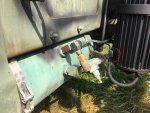
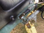
On my truck, right after that protection valve on the wet tank, there is a T fitting. The smaller line(circled in first pic) runs to the hydraulic manifold to supply air to the cab air suspension valve. The larger line runs directly to the passenger cab floor to feed CTIS and the fan control solenoid... The CTIS line is just out of sight behind it... you can just see the big line to ctis all the way to the right in the second picture...


7241D77C-9636-4649-8A6C-2D47687D04D7.jpegA769670C-B16B-4BBC-BA76-94D52533D55C.jpeg
 

tennmogger

Well-known member
Steel Soldiers Supporter
1,579
542
113
Location
Greenback, TN
You the man!!! This is one of those posts that will be around to help others for a long time.
Thank you greatly and I'll let you know how this turns out.
I figure if I put charged air line from my shop compressor into one of the drains on the wet tank I should be able to work without noise and go uninterrupted in the execution of diagnostics. Merry Christmas. Lugnuts
Ronmar is one of the good tech guys who says more than "go read the manual and follow the troubeshooting"!
 
Top
AdBlock Detected

We get it, advertisements are annoying!

Sure, ad-blocking software does a great job at blocking ads, but it also blocks useful features of our website like our supporting vendors. Their ads help keep Steel Soldiers going. Please consider disabling your ad blockers for the site. Thanks!

I've Disabled AdBlock
No Thanks