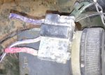
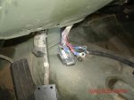
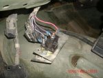
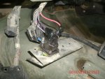
Not quite sure from the photos, but it looks like the purple wire might be where the red one goes, and the red one might be where the purple one goes. Or the other way around. I could be wrong.
For future readers, when doing this mod, make sure that you solder the wire ends to the terminal and skink tube the connection, otherwise a crimp on connector can become loose over time due to the wires and terminals heating up and expanding and contracting, creating a loose connection and possible arcing and sparking.
The connections also will increase their resistance to current flow as most metals' molecular make up forces their operating characteristics when conducting electricity into a positive temperature coefficient. Resulting in an increase in current with the higher temperatures. You can read about that here.
Temperature coefficient - Wikipedia
It is also a good idea to replace the GEN2 relay when doing this mod as the heavier coils in the new relay will draw slightly more amperage resulting in a stronger magnetic field in the alternators, due to them charging the batteries at a now increased rate, at the expense of more amperage draw to the exciter circuit to the alternators, causing a heavier load to be placed on the contacts of the GEN2 relay...
...and the GEN1 and GEN2 light bulb connections.
It also seems that there is an A3 in the photos.
.


