@CallMeColtA mechanical gauge can also be added at the oil pressure sender... I did it on my machine, based off info in this forum. Under $100 for all parts, including the gauge (precovid)... knowing for certain your pressure is a no brainer investment to me.
View attachment 903248
View attachment 903249
-
Steel Soldiers now has a few new forums, read more about it at: New Munitions Forums!
First MEP 803A, fix up help
- Thread starter Pirotess
- Start date

More options
Who Replied?- 3,963
- 6,431
- 113
- Location
- MA
That's the perfect place to put one for sure!! Finding a quality gauge is always interesting. I have the automotive style that has the long hose so it can be popped up under a wiper arm when driving. I don't use them much anymore though. I assume to install that it is a few 1/4 inch pipe threaded attachments.
Installed Mechanical Oil Pressure Gauge on MEP-803A
Curiosity got the better of me on the oil pressure gauge accuracy. I've been wanting to flush and change oil and decided to add a mechanical oil pressure gauge. I drained the unit, refilled with ATF, and ran it up to temp with no load. Drained again and refilled with Motorcraft 15W40 Diesel...
www.steelsoldiers.com
Pirotess
Member
- 18
- 37
- 13
- Location
- Lavaca County, TX, USA
Just an update for today...
I like that analog oil gauge idea. I found the same Marshall one off Amazon and have that coming. Easier than making a temporary setup with a rental tool.
I tested the Frequency transducer and it is way out of spec. Instead of 100uA (60Hz) and 200uA (65Hz), it is reading 297uA and 417uA in my test.
Can those be repaired?
My Coolant Gauge is kinda ok?
On the low test (117-143 ohms), it said 116-164º, but on my gauge I got around 140-155º. On the high test (59-72 ohms), it was supposed to get 156-204º, and my gauge read 175-179º.
It's kinda in spec, but I am not getting the range I am supposed to?
I took an IR temp at the thermostat and it was fairly close with the gauge though when it was at 160º.
The Oil pressure Gauge was similar. The low test (93-113 ohms, 32-48 psi) gave me 39-49psi. The high test (30-37 ohms, 72-80psi) gave me 80-80psi.
Again, kinda in spec but the range spread is not there...
I will see how it matches with the analog gauge when it comes in.
The Ammeter Gauge looks Ok, maybe just an adjustment on the screw I guess. But the load doesn't match.
The test gave 0.251A at 27% (12A load on each leg) (should be 33.5% at 0.251A, but 23% according to 12A load?) and 0.450A at 55% (should be 60% at 0.450A).
I may need to do this test again though. Being 108ºF today, the heaters would not stay on and kept fluctuating. I was not able to get a good amp reading any higher on the draw since only a couple of heaters worked.
The Shunt tested ok at 0.1 ohms, it was a 20A 50mV model. Could it still be bad and cause this higher ammeter reading? Is that the correct one?
The Voltage Potentiometer was good and went 0-5Kohms, but it was hard to dial in for the tests and drifted a little. Not sure about it.
Another thing I noticed, I switched the AC Interrupt Relay several times today, and the voltages on the output seemed to move around when I did so. At one point, it was fairly balanced between the two, but it was under a light load so I am not sure. I might have to figure out how to open it up and clean it. I think someone did that before here.... can't find it right now. Is there a diagram or pictures anywhere?
Need to get a thermostat and do a flush. Going to try and test some of the senders too.
Icesythe7
Active member
- 147
- 223
- 43
- Location
- Indiana, USA
The senders and gauges are easy to verify if you use a voltage divider like https://ohmslawcalculator.com/voltage-divider-calculator the source voltage will be 12v (the gauge reduces it) the gauges ohms is 33 and the second ohm reading is the reading from the sender, the gauges needle will be all the way to the left at 10v will be exactly middle at 5v and at 0v will be all the way to the right, so for exampleJust an update for today...
I like that analog oil gauge idea. I found the same Marshall one off Amazon and have that coming. Easier than making a temporary setup with a rental tool.
I tested the Frequency transducer and it is way out of spec. Instead of 100uA (60Hz) and 200uA (65Hz), it is reading 297uA and 417uA in my test.
Can those be repaired?
My Coolant Gauge is kinda ok?
On the low test (117-143 ohms), it said 116-164º, but on my gauge I got around 140-155º. On the high test (59-72 ohms), it was supposed to get 156-204º, and my gauge read 175-179º.
It's kinda in spec, but I am not getting the range I am supposed to?
I took an IR temp at the thermostat and it was fairly close with the gauge though when it was at 160º.
The Oil pressure Gauge was similar. The low test (93-113 ohms, 32-48 psi) gave me 39-49psi. The high test (30-37 ohms, 72-80psi) gave me 80-80psi.
Again, kinda in spec but the range spread is not there...
I will see how it matches with the analog gauge when it comes in.
The Ammeter Gauge looks Ok, maybe just an adjustment on the screw I guess. But the load doesn't match.
The test gave 0.251A at 27% (12A load on each leg) (should be 33.5% at 0.251A, but 23% according to 12A load?) and 0.450A at 55% (should be 60% at 0.450A).
I may need to do this test again though. Being 108ºF today, the heaters would not stay on and kept fluctuating. I was not able to get a good amp reading any higher on the draw since only a couple of heaters worked.
The Shunt tested ok at 0.1 ohms, it was a 20A 50mV model. Could it still be bad and cause this higher ammeter reading? Is that the correct one?
The Voltage Potentiometer was good and went 0-5Kohms, but it was hard to dial in for the tests and drifted a little. Not sure about it.
Another thing I noticed, I switched the AC Interrupt Relay several times today, and the voltages on the output seemed to move around when I did so. At one point, it was fairly balanced between the two, but it was under a light load so I am not sure. I might have to figure out how to open it up and clean it. I think someone did that before here.... can't find it right now. Is there a diagram or pictures anywhere?
Need to get a thermostat and do a flush. Going to try and test some of the senders too.

if the sender says 25 ohms that results in an output voltage of ~5.2v which you can then verify at the back of the gauge between the gauges ground and the gauges signal wire, you could then verify the needle is in the middle of the gauge which would mean the gauge is working properly and maybe the sender is "working" but the resistance is wrong (which is the case in my coolant sender)
- 17,503
- 25,907
- 113
- Location
- Burgkunstadt, Germany
People, you are making a mountain out of a mole hill.
I tested the Frequency transducer and it is way out of spec. Instead of 100uA (60Hz) and 200uA (65Hz), it is reading 297uA and 417uA in my test.
Can those be repaired? NO.
My Coolant Gauge is kinda ok?
On the low test (117-143 ohms), it said 116-164º, but on my gauge I got around 140-155º. On the high test (59-72 ohms), it was supposed to get 156-204º, and my gauge read 175-179º.
It's kinda in spec, but I am not getting the range I am supposed to?
I took an IR temp at the thermostat and it was fairly close with the gauge though when it was at 160º.
The Oil pressure Gauge was similar. The low test (93-113 ohms, 32-48 psi) gave me 39-49psi. The high test (30-37 ohms, 72-80psi) gave me 80-80psi.
Again, kinda in spec but the range spread is not there...
I will see how it matches with the analog gauge when it comes in. The gauges are close enough for gov. work. They were never meant to be as exact as you all WANT them. If it works, its good enough. Its in the ball park. If you want perfection, then go spend a lot of money.
The Ammeter Gauge looks Ok, maybe just an adjustment on the screw I guess. But the load doesn't match.
The test gave 0.251A at 27% (12A load on each leg) (should be 33.5% at 0.251A, but 23% according to 12A load?) and 0.450A at 55% (should be 60% at 0.450A). Same thing here. And you should get some contact cleaner and spray and make sure S8 is cleaned out real good. It will maybe change your readings.
I may need to do this test again though. Being 108ºF today, the heaters would not stay on and kept fluctuating. I was not able to get a good amp reading any higher on the draw since only a couple of heaters worked.
The Shunt tested ok at 0.1 ohms, it was a 20A 50mV model. Could it still be bad and cause this higher ammeter reading? Is that the correct one? Look in the parts manual? Look at the shunt. What could go wrong? Something might be loose, or the link between the post is broken. But thats about it.
The Voltage Potentiometer was good and went 0-5Kohms, but it was hard to dial in for the tests and drifted a little. Not sure about it. Try rotating it 100 times back and forth. Might help. This set is NOT a precise Power generator.
Another thing I noticed, I switched the AC Interrupt Relay several times today, and the voltages on the output seemed to move around when I did so. At one point, it was fairly balanced between the two, but it was under a light load so I am not sure. I might have to figure out how to open it up and clean it. I think someone did that before here.... can't find it right now. Is there a diagram or pictures anywhere? This is something a lot of times happens. You dont need a diagram, nor is it hard. Often water got in them and caused corrosion. The relay doesn't always operate correctly. Or maybe some foolish person turned off the gen set, while under load. The contacts can become pitted that way. Open it up and look around. Clean as needed. There are lots of threads dealing with just this problem.
Icesythe7
Active member
- 147
- 223
- 43
- Location
- Indiana, USA
Not meaning to argue but on the topic of the gauges, I don't think anyone expects perfection but if the senders are out of spec per the TM's then they will only get more and more off over time I see no harm in replacing them like the TM states to do when they are out of spec given they are like $9People, you are making a mountain out of a mole hill.
I tested the Frequency transducer and it is way out of spec. Instead of 100uA (60Hz) and 200uA (65Hz), it is reading 297uA and 417uA in my test.
Can those be repaired? NO.
My Coolant Gauge is kinda ok?
On the low test (117-143 ohms), it said 116-164º, but on my gauge I got around 140-155º. On the high test (59-72 ohms), it was supposed to get 156-204º, and my gauge read 175-179º.
It's kinda in spec, but I am not getting the range I am supposed to?
I took an IR temp at the thermostat and it was fairly close with the gauge though when it was at 160º.
The Oil pressure Gauge was similar. The low test (93-113 ohms, 32-48 psi) gave me 39-49psi. The high test (30-37 ohms, 72-80psi) gave me 80-80psi.
Again, kinda in spec but the range spread is not there...
I will see how it matches with the analog gauge when it comes in. The gauges are close enough for gov. work. They were never meant to be as exact as you all WANT them. If it works, its good enough. Its in the ball park. If you want perfection, then go spend a lot of money.
The Ammeter Gauge looks Ok, maybe just an adjustment on the screw I guess. But the load doesn't match.
The test gave 0.251A at 27% (12A load on each leg) (should be 33.5% at 0.251A, but 23% according to 12A load?) and 0.450A at 55% (should be 60% at 0.450A). Same thing here. And you should get some contact cleaner and spray and make sure S8 is cleaned out real good. It will maybe change your readings.
I may need to do this test again though. Being 108ºF today, the heaters would not stay on and kept fluctuating. I was not able to get a good amp reading any higher on the draw since only a couple of heaters worked.
The Shunt tested ok at 0.1 ohms, it was a 20A 50mV model. Could it still be bad and cause this higher ammeter reading? Is that the correct one? Look in the parts manual? Look at the shunt. What could go wrong? Something might be loose, or the link between the post is broken. But thats about it.
The Voltage Potentiometer was good and went 0-5Kohms, but it was hard to dial in for the tests and drifted a little. Not sure about it. Try rotating it 100 times back and forth. Might help. This set is NOT a precise Power generator.
Another thing I noticed, I switched the AC Interrupt Relay several times today, and the voltages on the output seemed to move around when I did so. At one point, it was fairly balanced between the two, but it was under a light load so I am not sure. I might have to figure out how to open it up and clean it. I think someone did that before here.... can't find it right now. Is there a diagram or pictures anywhere? This is something a lot of times happens. You dont need a diagram, nor is it hard. Often water got in them and caused corrosion. The relay doesn't always operate correctly. Or maybe some foolish person turned off the gen set, while under load. The contacts can become pitted that way. Open it up and look around. Clean as needed. There are lots of threads dealing with just this problem.
- 3,301
- 2,147
- 113
- Location
- Pemberton, N.J.
You are correct, if the sender is out of spec and it is 9.00 them replace it. BUT, you are expecting $9.00 senders and $25.00 meters to do the jobs of $50.00 senders and $500.00 meters and that is simply not going to happen. The gauges on these units tell the operator it is working satisfactorily enough to get the job done, and that is all he needs to know. The guys running these machines are not electrical engineers, and neither are you or you would not be asking these questions. You do not need to be an engineer to run this machine. No offense, but the machine is designed to do a basic job and that is what it is doing.
Icesythe7
Active member
- 147
- 223
- 43
- Location
- Indiana, USA
First I never asked the question another member did, and yet again noone is expecting perfection the reply was because Guyfang said that we are making a mountain out of a mole hill by the gauge being of by ~10% which (imo) could be an issue for quick information, if normal operating temp is 170-200 and gauges is working but slightly out of spec and reads 185 but in reality the temp is 205 then that small amount it is off may make someone think it is running normally when it is in fact starting to running hot.You are correct, if the sender is out of spec and it is 9.00 them replace it. BUT, you are expecting $9.00 senders and $25.00 meters to do the jobs of $50.00 senders and $500.00 meters and that is simply not going to happen. The gauges on these units tell the operator it is working satisfactorily enough to get the job done, and that is all he needs to know. The guys running these machines are not electrical engineers, and neither are you or you would not be asking these questions. You do not need to be an engineer to run this machine. No offense, but the machine is designed to do a basic job and that is what it is doing.
- 3,963
- 6,431
- 113
- Location
- MA
The gauge is for operator reference only, and does not control the coolant overtemp fault... So while I would also want it to read true on my machine, do know that the safety stop is separate from the readout.
Icesythe7
Active member
- 147
- 223
- 43
- Location
- Indiana, USA
Correct it is but we shouldn't be relying on that as a means of protecting the equipment, my only point was I feel like if the TM says it needs replaced we shouldn't be suggesting to others that it isn't a big deal is all...obviously anyone with any common sense knows you could remove the gauge entirely and run it however we should prolly follow what the TM states to do instead of basically saying it doesn't matter since that is up to the owner of the equipment, if they wanna leave it like it is then great if they wanna replace it then great but we should only be suggesting things that coincide with what the people that built the machine suggest lolThe gauge is for operator reference only, and does not control the coolant overtemp fault... So while I would also want it to read true on my machine, do know that the safety stop is separate from the readout.
- 3,301
- 2,147
- 113
- Location
- Pemberton, N.J.
Remember, those people in the military did not have to pay for the parts they were pulling out of the parts supply. And the manuals were written for guys right out of high school with very little or even no experience working on equipment. It is much easier to tell them to replace it than to take the readings with a grain of salt.
- 17,503
- 25,907
- 113
- Location
- Burgkunstadt, Germany
Not meaning to argue but on the topic of the gauges, I don't think anyone expects perfection but if the senders are out of spec per the TM's then they will only get more and more off over time I see no harm in replacing them like the TM states to do when they are out of spec given they are like $9
Your correct. On everything you wrote. But if a meter or sender is out of spec, a tad, or even more than a tad, then you can concentrate on other things, and put the meter on the to do list. The chart below, is an example, and this is my opinion, and I mean no disrespect to you or other's, but its a tad over done. I ran gen sets 24/7/365. We very rarely looked at temps. Why? If its too hot, it will shut down. If the fuel gage is off, well, since they all ate the same amount of fuel, they get filled up all at the same time. So the gage can be off. Just so long as it will run. We could not afford to stop running because of a high temp, it was not real world, for us. And I bet, should the lights go out, you would run it too. So please don't get your feathers ruffled. It's my opinion, and that something we all write a lot, in here. That's what a forum is for. Information, and discussion.
The senders and gauges are easy to verify if you use a voltage divider like https://ohmslawcalculator.com/voltage-divider-calculator the source voltage will be 12v (the gauge reduces it) the gauges ohms is 33 and the second ohm reading is the reading from the sender, the gauges needle will be all the way to the left at 10v will be exactly middle at 5v and at 0v will be all the way to the right, so for example
Icesythe7
Active member
- 147
- 223
- 43
- Location
- Indiana, USA
Right but we just simply have to remember we are not in the military anymore where these are meaningless and if an engine dies who cares it is not coming out of my paycheck...this is the real world and these machines are not "cheap" therefore relying on the automatic shutdown to be working (hopefully it does) to save the machine from killing itself seems silly when we could also have a more accurate gauge is all. A machine dying in the military who cares...a $3k - $4k machine dying out of your pocket over a $9 part that was off by 40 degrees so it seemed ok is a big deal (at least to me since I don't have 30 of them on standby for free.) I understand your point exactly and also mean no disrespect just was trying to keep us all in the realm of realism...again the odds of both failing pretty low for sure but if I can mitigate the risk of losing 3k for $9 and a periodic glance at the temp gauge (or oil pressure) I feel like that is the smartest move.Your correct. On everything you wrote. But if a meter or sender is out of spec, a tad, or even more than a tad, then you can concentrate on other things, and put the meter on the to do list. The chart below, is an example, and this is my opinion, and I mean no disrespect to you or other's, but its a tad over done. I ran gen sets 24/7/365. We very rarely looked at temps. Why? If its too hot, it will shut down. If the fuel gage is off, well, since they all ate the same amount of fuel, they get filled up all at the same time. So the gage can be off. Just so long as it will run. We could not afford to stop running because of a high temp, it was not real world, for us. And I bet, should the lights go out, you would run it too. So please don't get your feathers ruffled. It's my opinion, and that something we all write a lot, in here. That's what a forum is for. Information, and discussion.
Pirotess
Member
- 18
- 37
- 13
- Location
- Lavaca County, TX, USA
Thanks for the replies.
I just followed the TM guides on testing the gauges. I haven't worked on these before, so I wanted to post my findings and get a feel if that was normal or not. Sounds like is is Acceptable for these units.
I opened up the interrupter and the seal looked good and the contacts were pretty clean. I brass wire brushed them clean and reassembled.
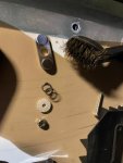
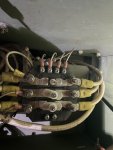
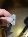
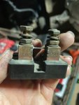
I could not find much info on the shunt part, but it looks original, so I am going to assume it is ok.
I got a can of deox/electronic cleaner and sprayed down that phase/voltage switch (S8 I believe?), and the S6 switch for the measurements. Moved them around and sprayed some more. Hopefully that cleaned them out.
So, I could not find any replacements online for this model 19260 frequency transducer, so I figured I would take a try at fixing it. I am not great at electronics repair, but I know some.
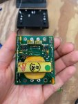
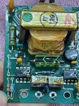
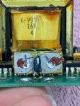
After desoldering, testing, and re-soldering way too many parts (had to test them out of circuit), most checked out fine. A couple of resistors had drifted a bit from spec, but not too bad. I decided to mess with the two potentiometers and hope that would do some good. I couldn't see all the traces to the pots, but It looked like they may adjust the 555 timer IC, so I figured they might be a fine tuning calibration.
Well, the output jumped all over the place when I touched those! Seems like there was wear or corrosion inside the pots somehow. I exercised them a lot, then adjusted them close to where they were originally and was able to get it working! While plugged it into the wall, I calibrated it to 100uA DC with the pots. The left one seemed to be more of a fine tuner, with the right being coarse. But I am not sure so I tried keeping them both close to the original marks.
I haven't tried it on the generator yet, but it seems to be good now. It is a little worse for wear thought, lol.
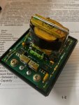
So, yea I think people could try to repair the Frequency Transducer 19260.
1. If yours is just out of spec, I would check the two grey adjustment potentiometers on the front. Mine were messed up inside and needed to be exercised. I also had to fine tune it a little, probably due to resistor drifting or the pots.
2. If you have no output, and nothing is obviously burnt, I would check the fine wires on the 120V/16V transformer leads. One may have just broken loose. Don't ask me why I had to figure that out, sigh...
Hope this helps someone.
Going to do the oil gauge mod next. And I ordered a new thermostat for when I flush the radiator. Still working on it.
I just followed the TM guides on testing the gauges. I haven't worked on these before, so I wanted to post my findings and get a feel if that was normal or not. Sounds like is is Acceptable for these units.
I opened up the interrupter and the seal looked good and the contacts were pretty clean. I brass wire brushed them clean and reassembled.


I could not find much info on the shunt part, but it looks original, so I am going to assume it is ok.

I got a can of deox/electronic cleaner and sprayed down that phase/voltage switch (S8 I believe?), and the S6 switch for the measurements. Moved them around and sprayed some more. Hopefully that cleaned them out.
So, I could not find any replacements online for this model 19260 frequency transducer, so I figured I would take a try at fixing it. I am not great at electronics repair, but I know some.


After desoldering, testing, and re-soldering way too many parts (had to test them out of circuit), most checked out fine. A couple of resistors had drifted a bit from spec, but not too bad. I decided to mess with the two potentiometers and hope that would do some good. I couldn't see all the traces to the pots, but It looked like they may adjust the 555 timer IC, so I figured they might be a fine tuning calibration.
Well, the output jumped all over the place when I touched those! Seems like there was wear or corrosion inside the pots somehow. I exercised them a lot, then adjusted them close to where they were originally and was able to get it working! While plugged it into the wall, I calibrated it to 100uA DC with the pots. The left one seemed to be more of a fine tuner, with the right being coarse. But I am not sure so I tried keeping them both close to the original marks.
I haven't tried it on the generator yet, but it seems to be good now. It is a little worse for wear thought, lol.

So, yea I think people could try to repair the Frequency Transducer 19260.
1. If yours is just out of spec, I would check the two grey adjustment potentiometers on the front. Mine were messed up inside and needed to be exercised. I also had to fine tune it a little, probably due to resistor drifting or the pots.
2. If you have no output, and nothing is obviously burnt, I would check the fine wires on the 120V/16V transformer leads. One may have just broken loose. Don't ask me why I had to figure that out, sigh...
Hope this helps someone.
Going to do the oil gauge mod next. And I ordered a new thermostat for when I flush the radiator. Still working on it.
Last edited:
Icesythe7
Active member
- 147
- 223
- 43
- Location
- Indiana, USA
Woo good deal, if you still have good access to it might be a good idea to see if you can find a part number or if not grab input voltage and the ohm range of the pot so we can see if we can find a good replacement on digikey/mouser for future boards also what is the footprint just the standard 3 pin 2.54mm spacing?Thanks for the replies.
I just followed the TM guides on testing the gauges. I haven't worked on these before, so I wanted to post my findings and get a feel if that was normal or not. Sounds like is is Acceptable for these units.
I opened up the interrupter and the seal looked good and the contacts were pretty clean. I brass wire brushed them clean and reassembled.
View attachment 903409View attachment 903410View attachment 903411
I could not find much info on the shunt part, but it looks original, so I am going to assume it is ok.
View attachment 903408
I got a can of deox/electronic cleaner and sprayed down that phase/voltage switch (S6 I believe?), and the S8 switch for the measurements. Moved them around and sprayed some more. Hopefully that cleaned them out.
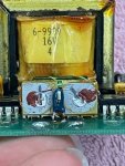
So, I could not find any replacements online for this model 19260 transducer, so I figured I would take a try at fixing it. I am not great at electronics repair, but I know some.
View attachment 903412View attachment 903415View attachment 903414
After desoldering, testing, and re-soldering way too many parts (had to test them out of circuit), most checked out fine. A couple of resistors had drifted a bit from spec, but not too bad. I decided to mess with the two potentiometers and hope that would do some good. I couldn't see all the traces to the pots, but It looked like they may adjust the 555 timer IC, so I figured they might be a fine tuning calibration.
Well, the output jumped all over the place when I touched those! Seems like there was wear or corrosion inside the pots somehow. I exercised them a lot, then adjusted them close to where they were originally and was able to get it working! While plugged it into the wall, I calibrated it to 100uA DC with the pots. The left one seemed to be more of a fine tuner, with the right being coarse. But I am not sure so I tried keeping them both close to the original marks.
I haven't tried it on the generator yet, but it seems to be good now. It is a little worse for wear thought, lol.
View attachment 903422
So, yea I think people could try to repair these.
If yours is just out of spec, I would check the two grey adjustment potentiometers on the front. Mine were messed up inside and needed to be exercised. I also had to fine tune it a little, probably due to resistor drifting or the pots.
If you have no output, and nothing is obviously burnt, I would check the fine wires on the 120V/16V transformer leads. One may have just broken loose. Don't ask me why I had to figure that out, sigh...
Hope this helps someone.
Going to do the oil gauge mod next. And I ordered a new thermostat for when I flush the radiator. Still working on it.
Pirotess
Member
- 18
- 37
- 13
- Location
- Lavaca County, TX, USA
Icesythe7
Active member
- 147
- 223
- 43
- Location
- Indiana, USA
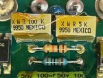
perfect here is the link to them for future people reading thisI already have everything re-soldered, but I can see the part numbers. Looks like a 5K pot and a 100k pot.
I would say there are probably part numbers 72XWR5KLFTB and 72XWR100KLF .
View attachment 903453View attachment 903454
72XWR5KLFTB
72XWR100KLF
- 3,963
- 6,431
- 113
- Location
- MA
The part numbers are helpful. Only issue is there no stock anywhere in the world on either part currently, and the minimum order is 900 
Maybe there are equivalents out there.
Maybe there are equivalents out there.
Icesythe7
Active member
- 147
- 223
- 43
- Location
- Indiana, USA
these should be equivalentThe part numbers are helpful. Only issue is there no stock anywhere in the world on either part currently, and the minimum order is 900
Maybe there are equivalents out there.
https://www.digikey.com/en/products/detail/bourns-inc./3296W-1-502RLF/6134010
https://www.digikey.com/en/products/detail/bourns-inc./3296W-1-104ALF/18718391
- 3,301
- 2,147
- 113
- Location
- Pemberton, N.J.
I admire the skill and patience of you guys that can take these electronics apart and make them work. AND track down replacements!!
Icesythe7, I now understand why you are always wanting to put the replacement meters and senders in. LOL.
Icesythe7, I now understand why you are always wanting to put the replacement meters and senders in. LOL.
- 112,601members
- 166,187threads
- 2,340,742posts
- 966online users

