• Steel Soldiers now has a few new forums, read more about it at: New Munitions Forums!

  • Microsoft MSN, Live, Hotmail, Outlook email users may not be receiving emails. We are working to resolve this issue. Please add support@steelsoldiers.com to your trusted contacts.

FLU419 SEE HMMH HME Owners group

alpine44

Member
403
17
18
Location
Asheville, NC - Elkton, MD
Continuing to fix small problems and replace most fluids. It is a long but worthwhile process. The nasty rust colored brake fluid was definitely overdue for replacement. I have noticed the front fan on the hydraulic oil cooler comes on, but the back one does not work. Haven't had a chance to look at it yet. Does anyone know if they are separately controlled by the front and rear hydraulic systems, or should they both come on at the same time no matter what? I finally was able to take the beast for a test drive down the road and put a few miles on it. When I parked it the front hydraulic tank seemed fairly hot even with the fan running. It could just be normal, but my experience with this tractor is very limited, so want to make sure.
Make sure the tool circuit is switched off. The front pump always runs when the engine does. When loader and tools are not in use, the output from the pump drains straight into the tank with the least possible friction and resulting heat. If either one of the spools behind the cab is out of the "neutral" position, the restricted flow is going to generate more heat. For testing you can disconnect the solenoid leads of the valve section that only has one solenoid.
 

peakbagger

Well-known member
734
360
63
Location
northern nh
Just in case you haven't checked the obvious, swap the leads on the fans at the electrical terminal block at the base of the fan and see if the opposite fan runs. That rules out that you have bad fan (which is very common).
 

FarmMOG

Member
42
1
8
Location
Texas/Oklahoma
The cooler is for the rear system only, as far as I can tell, as they seem to be completely separate systems. And the fans are wired together, so both are supposed to run when the temp sensor decides that they should.
I don't think I ever thought to check if the front tank got hot, but if things are working like they should, the only way I know of to make that fluid hot would be to work the loader fairly hard.
But what really makes me curious is how you ended up with the fan running after a test drive. Mine takes a decent amount of work with the backhoe at higher ambient temperatures for the fans to come on. Or, running the snow blower (which takes all the power the rear system can muster) for an hour or so. In other words, my fans rarely come on. Was your PTO accidentally engaged during the drive?

Thinking more about this, you got both the front and rear systems hot (which is subjective, except that the cooling fan came on, so that's definitely hot) which makes me wonder if there are severe restrictions in both systems. But the rear one shouldn't know, or care, as long as the PTO isn't engaged. You definitely have my curiosity pegged now.
I traced the plumbing and both the front and rear hydraulic systems go to the cooler. The fluid is kept separate from each system. The rear PTO was definitely not engaged, and the rear hydraulic system was not hot at all. The front hydraulic system has a problem with the loader control valve body, and I have someone coming to take a look at it, so that might be a restriction that is causing the fluid to heat up. I will have to trouble shoot the rear fan and either repair or replace it.
 

FarmMOG

Member
42
1
8
Location
Texas/Oklahoma
Make sure the tool circuit is switched off. The front pump always runs when the engine does. When loader and tools are not in use, the output from the pump drains straight into the tank with the least possible friction and resulting heat. If either one of the spools behind the cab is out of the "neutral" position, the restricted flow is going to generate more heat. For testing you can disconnect the solenoid leads of the valve section that only has one solenoid.
The tool switch was turned off, and I can tell it pressurizes the system with corresponding increase in RPM when activated. I am not sure what you mean about the spools in the neutral position. The valve body does have a problem with lowering the loader arm, and sure could have some sort of restriction causing the fluid to heat up. A tractor mechanic is coming out to take a look at it and try to figure out what is wrong.
 

FarmMOG

Member
42
1
8
Location
Texas/Oklahoma
Just in case you haven't checked the obvious, swap the leads on the fans at the electrical terminal block at the base of the fan and see if the opposite fan runs. That rules out that you have bad fan (which is very common).
I never thought about that, but it should be a quick and easy check for both the wiring and fan itself. Thanks.
 

rtrask

Well-known member
342
251
63
Location
San Luis Valley, Colorado
Once you have the correct key for the master switch (which does interrupt the negative side), your starter may work.
EI has them. And get a battery box/hood key while you're at it, if you don't have one already.

Edit: If you want to make your own key for the master switch rather than wait for one, let me know and I'll give you the important measurements.
There's not much to it if you make your own, but any old key that fits may not be good for the switch, I've learned.
Modifying an existing "universal" (usually they have a red handle) key may be the quickest way.
I not yet bought a master disconnect key from EI. They want 16.50 for the key and and nearly that to ship it. I figure I can manufacture one for less than $2 I have gotten by with out it till now, because once the SEE started it did not matter. Now that I am wading into the electrical issues, I need to connect the battery to the rest of the system :???:. So if you or anyone else is willing to give me the diameter of the plunger, and the distance from the cross pin to the bottom of the plunger it would be greatly appreciated.

I will probably buy one once I work up my next order from EI, but till then.
 

The FLU farm

Well-known member
Steel Soldiers Supporter
3,357
1,361
113
Location
The actual midwest, NM.
Now that I am wading into the electrical issues, I need to connect the battery to the rest of the system :???:. So if you or anyone else is willing to give me the diameter of the plunger, and the distance from the cross pin to the bottom of the plunger it would be greatly appreciated.
You can use a jumper cable to bypass the master disconnect for now.
I can give you the key measurements tomorrow. No pun intended.

And speaking of expensive keys, I have a couple of dirt cheap hood/battery box keys in the works.
 

lurkMcGurk

Member
55
17
8
Location
Bangor,Maine
And speaking of expensive keys, I have a couple of dirt cheap hood/battery box keys in the works.[/QUOTE]

That is something I would be interested in and possibly attach those beepers to because they are hard to find when dropped in grass!!!!!
 

The FLU farm

Well-known member
Steel Soldiers Supporter
3,357
1,361
113
Location
The actual midwest, NM.
Okay, I'll try to get them done somewhat soon. Or at least show the parts that still needs to be welded up.
Dirt cheap Craftsman 8mm multi sockets and bent, ground/filed rod, basically. Also, a modified train key version.
Plus I found $5 ratcheting 10mm wrenches some time back, perfect for the bleeder screws. They're so perfect that I haven't needed to use even one of the three I bought yet.
 

rtrask

Well-known member
342
251
63
Location
San Luis Valley, Colorado
I got the dimensions of the key from a PM I sent.
Center hole is .240" from bottom surface. Diameter of that section is .430" and that thicker section is about .680" long. Handle section diameter is .315". There is a .210" long recess to .395" on the thicker section where the pin is located. The pin diameter is .158".
Hope that helps.
Thanks to everyone especially Alpine44

in mm it translates to Center hole is 6 mm from bottom surface. Diameter of that section is 11 mm and that thicker section is about 17 mm long. Handle section diameter is 8 mm. There is a 5 mm long recess to 10 mm on the thicker section where the pin is located. The pin diameter is 4 mm.

Expedition Imports sells them, and also provides a handy picture to go with the dimensions.
https://expedition-imports.com/0005451635
 
Last edited:

Foxyjosh

Member
53
0
6
Location
Northeast /OH
The cooler is for the rear system only, as far as I can tell, as they seem to be completely separate systems. And the fans are wired together, so both are supposed to run when the temp sensor decides that they should.
I don't think I ever thought to check if the front tank got hot, but if things are working like they should, the only way I know of to make that fluid hot would be to work the loader fairly hard.
But what really makes me curious is how you ended up with the fan running after a test drive. Mine takes a decent amount of work with the backhoe at higher ambient temperatures for the fans to come on. Or, running the snow blower (which takes all the power the rear system can muster) for an hour or so. In other words, my fans rarely come on. Was your PTO accidentally engaged during the drive?

Thinking more about this, you got both the front and rear systems hot (which is subjective, except that the cooling fan came on, so that's definitely hot) which makes me wonder if there are severe restrictions in both systems. But the rear one shouldn't know, or care, as long as the PTO isn't engaged. You definitely have my curiosity pegged now.
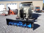
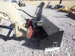
Can you please post pictures of the snowblower?
 

Another Ahab

Well-known member
18,007
4,582
113
Location
Alexandria, VA
I believe there are some pics on the thread here, if you go back far enough.

But it's always easier, and a treat, if we get some instant pics here and now!
 

alpine44

Member
403
17
18
Location
Asheville, NC - Elkton, MD
Did anybody figure out how the suspension lockout on the HMMH actually works?

The front shocks of the HMMH are different and have two hoses each attached to them that go to an electric pump unit. One possibility to make this work would be to pump oil into the lower cylinder portion of a conventional shock via the lower hose and use the upper hose as a drain. If there is sufficient flow, pressure will build below the piston of the shock despite the damping orifice and the axle will be pulled to the bumper stop. The upper hose would drain the oil leaking past the orifice back to the tank. This setup would require the pump to run continuously when lockout is engaged.

Does this sound like what is actually happening on a HMMH?
 

The FLU farm

Well-known member
Steel Soldiers Supporter
3,357
1,361
113
Location
The actual midwest, NM.
Kinda. Except that the fluid is pumped into the top to lower it (gotcha!)
The pump in the HMMH only runs until the suspension is compressed, so there's probably no actual shock absorber function in them, with normal orifices. Still, the HMMH handles like a sports car compared to a SEE, but that fact I always contributed to a lower center of gravity, and less weight.
 

alpine44

Member
403
17
18
Location
Asheville, NC - Elkton, MD
Kinda. Except that the fluid is pumped into the top to lower it (gotcha!)
The pump in the HMMH only runs until the suspension is compressed, so there's probably no actual shock absorber function in them, with normal orifices. Still, the HMMH handles like a sports car compared to a SEE, but that fact I always contributed to a lower center of gravity, and less weight.
What would happen if the lines were reversed on the shock? Could the HMMH shock absorbers be used to raise OR lower the front of the vehicle?
 

The FLU farm

Well-known member
Steel Soldiers Supporter
3,357
1,361
113
Location
The actual midwest, NM.
What would happen if the lines were reversed on the shock? Could the HMMH shock absorbers be used to raise OR lower the front of the vehicle?

I don't see why that wouldn't work. But while I've been concentrating on getting them lower (by using different tires or otherwise) it would still be easier and cheaper to use hydraulic cylinders, I think.
 

Foxyjosh

Member
53
0
6
Location
Northeast /OH
Transmission Saga

Well, I'm digging more into the transmission.

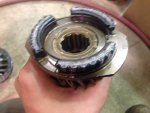
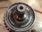
What was a promising outlook has quickly turned into a FUBAR diagnosis. The machine was stuck in gear because the transmission got so hot that one of the syncromesh friction welded itself together. Also, almost all the bearings have been fried.
Here is both sides of the syncro SyncromeshA.jpgSyncromeshB.jpg

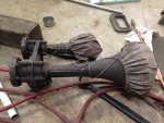
On a side note, I had a loco motive into buying a used set of air horns for the mog. There should be enough air in the tank to power them.
Horn.jpg
 
Top
AdBlock Detected

We get it, advertisements are annoying!

Sure, ad-blocking software does a great job at blocking ads, but it also blocks useful features of our website like our supporting vendors. Their ads help keep Steel Soldiers going. Please consider disabling your ad blockers for the site. Thanks!

I've Disabled AdBlock
No Thanks