Plowboy,
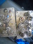
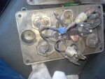
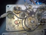
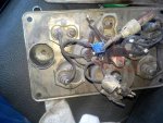
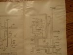
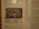
This is my understanding of the schematic...The molded splice is fed from #27 wire, which is switched battery voltage-i.e. when the ignition is off no voltage, and when it is on, voltage is supplied to all the gauges-temp, fuel, brake air, oil press through the molded plug-i didnt know that the g749 used a air brake pressure sending unit(figured it was hard piped). from there each respective gauge takes the raw voltage and uses that to read what is going on. As a example-a fuel sender has a resistor that increases or decreases in resistance depending on the fuel level in tank. So you see two connections-power to the gauge, and the wire going to the sender that basically through resistance level of the sensor, gets the gauge to read what the fuel level is. Back on track-#27 is wired back to the ignition switch that is landed on the same terminal as wire #85. If we follow 85 that goes to the low air pressure warning. Looking at the switch again there is wire #12 which goes tho the distributor(with built in coil) and while the schematic doesnt show it, my guess is #12 is wired to the plus(+) of the coil. Finally the ignition switch has wire #11 which goes to the + battery connection, or on early schematic goes to the ARM connection on voltage regulator--suffice to say it is hooked to battery voltage. So putting it together from the battery...Plowboy climbs into goose to go for a drive to one of his many events. Voltage is waiting to be switched on at #11. Ignition switch is turned-voltage is sent to distributor(#12), waiting for the engine to turn, low air pressure warning is activated(#85)(if goose leaks air and air is low enough), voltage is sent through #27 to molded plug in I/C and all guages bounce to life indicating conditions at hand. One other item not covered is #27 is spliced to #76 which if followed energizes the fuel pump. Plowboy engages the starter. The points activate the ignition coil sending voltage to each spark plug as necessary. Goose fires up, And life is good on the northern Alberta G749 farm. haha. Hope that explaination helps. I believe the G749 is using a voltmeter gauge-meaning it indicates voltage present in the system. There is another type of gauge called an ammeter gauge, but thats a whole different discussion. #8 goes to the voltage regulator, where it reads voltage present in the system with generator working. Through #27(and the molded plug) battery voltage is present(with key on). My hunch is someone spliced #27 and #8 just to get a more consistent voltage reading? Needless to say, I don't anticipate a splice from #8 to #27 being problematic, however the schematic doesnt show one, so why have it there. Hope that isnt too confusing.


