• Steel Soldiers now has a few new forums, read more about it at: New Munitions Forums!

  • Microsoft MSN, Live, Hotmail, Outlook email users may not be receiving emails. We are working to resolve this issue. Please add support@steelsoldiers.com to your trusted contacts.

GEN#1 light wont come on at all

D T

New member
46
0
0
Location
Ca.
my GEN#1 light has always worked perfectly,my GEN#2 light has been intermitant,bad Alt. I think,so I asked my neighbor to test and see if Alt.#2 was putting anything out,VOM meter,red to red,I told him to ground to #2 battery,NOT TO THE TRUCK,so what did he imediatlly do,ground it to the truck :-x,#1 Alt seems to still be charging but I cant get the #1 light to come on at all now,checked light ...good,checked socket...good,but no light .any Ideas.
of corse do the key on/key off test at the altinators,I will as soon as I can find someone to help without running me down
 

Barrman

Well-known member
5,239
1,730
113
Location
Giddings, Texas
With the truck running, check each battery individually. With it running, 14.4 volts is what the reading will be with a good alternator. Should be 12.4-12.6 volts with the truck not running and the key off.

What does your in dash volt meter say?

If one or both of the batteries is not getting up over 14 volts with the truck running. Turn is off and start checking the wires at the alternator and determine if it is a truck problem or an alternator problem.
 

D T

New member
46
0
0
Location
Ca.
when i got the truck the amp guage didnt work,then it started working between the yellow and green ,#1 light would come on at start ,but not #2 light ,then I got the #2 system working ,"all was good"the guage stayed around the top of the green,then #2 stoped working ,putting guage back to between the yellow and the green,thats when I got the idea to get my neighbor to throw his vom on my #2 system altinator just to see if it was putting anything out,thats when he grounded it ...puting 100 amps into the negitive side of the #1 system...now no#1 light but the guage stays between the yellow and green like #1 is still charging,Ill do the key on ...key off test and report back,thanks
 

Barrman

Well-known member
5,239
1,730
113
Location
Giddings, Texas
Right at the yellow and green line is an indication that 1 of the alternators is working and you have around 26 volts in the system. My #2 alternator was suffering from a bad diode trio when I got the truck. Since that battery is only used for starting, I went ahead and drove the truck while waiting for parts. I measured system volts and got to learn what the gauge translates to in numbers. Bottom of the yellow is no charge going on and around 24 volts.

DVOM's are cheap now days. As in less than $10 for one that will work for years. Get one, stick it into the battery terminals and do all the test yourself. Less gets lost in translation that way.
 

D T

New member
46
0
0
Location
Ca.
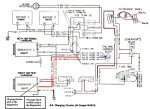
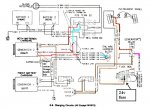
no juice at the GEN#1 brown wire with key on ,everything else checked out,#2 altinator is intermitant,I think that alt is bad ,I think #1 alt is not getting exciter voltage,I need to follow that circuit,any suggestions,Thanks
batteries sitting there 12.5 each
charging 14.7-27
 

Warthog

Moderator
Super Moderator
Steel Soldiers Supporter
13,774
231
63
Location
OKC, OK
The bulb for GEN1 is bad. Without it the circuit will not excite.

It could be the bulb, circuit board, wiring. Most likely a dirty contact on the bulb.
 

Attachments

D T

New member
46
0
0
Location
Ca.
thanks to both you guys,Im going to investigate the dash and wires leading that direction ,I think by circuit board you are refering to the back of the insturment cluster,Im on it,thanks again
 

Barrman

Well-known member
5,239
1,730
113
Location
Giddings, Texas
Yes, treat it with tender care and respect. Those little contact ends will fall off if you look at them wrong. I have found super glue is a great way to hold them to the circuit while you solder them back together though.

You can change all the bulbs on the cluster with it in the truck. You might get a shoulder cramp doing it, but it can be done. Done with success is a different story. I would suggest since the truck is new to you that pulling the dash pad off and then the gauge custer off would be best. Look up the thread Warthog made a few months ago about decoding the instrument cluster. Set it up on your kitchn table, take each bulb out, clean the holder and the contact on the circuit mat and start energizing every single bulb/circuit on the cluster once the bulbs are back in. Put it all back in the truck after every connection you can see has been cleaned and have happy driving.
 
Last edited:

D T

New member
46
0
0
Location
Ca.
Warthog...bullseye...I sawped my 2 lights and GEN#1 light started working,that was the first thing I tested,and visualy the filimint was intact,but this time I got no continuity,now Im on to the #2 side,Im getting exciter voltage so I think I need a rebuild kit. The m-1008 has 27,000 miles and when the army kicked it out they put new alternators on it but the wires to the #2 alternator were very very loose ,so I think it got damaged.I have every intention of pulling the dash ,cleaning everything,and do the relay upgrade at that time. my other m-1008 has been blowing the diodeon the GP controll board ,I got a new GP harness and a new GPRelay,now I have to solder some components on the circuit board and see what I get .
Warthog...thanks Barrman...thanks
 

D T

New member
46
0
0
Location
Ca.
A couple of more things I dont quite understand ... is there a ground wire going to/from the Pass. side alternator?...and my truck has the original GPRelay,with big rubber gromets inorder to insulate it from the body,but the upgrade GPR is usualy screwed directly to the firewall,what gives? THANKS
 

mistaken1

New member
1,467
6
0
Location
Kansas City, KS
A couple of more things I dont quite understand ... is there a ground wire going to/from the Pass. side alternator?...and my truck has the original GPRelay,with big rubber gromets inorder to insulate it from the body,but the upgrade GPR is usualy screwed directly to the firewall,what gives? THANKS
The passenger side alternator should not be grounded to the chassis.

The GP relay should have (obviously) an isolated load circuit and the coil is isolated as well. DO NOT not install a replacement relay that has one side of the coil grounded. The control system completes the coil circuit to ground to actuate the GP relay. As long as the coil is isolated from the case the case can be directly attached to the chassis without issue.

Are the rubber grommets for electrical isolation or vibration isolation?
 

D T

New member
46
0
0
Location
Ca.
thanks I was trying to figure out what wire is the negative on the #2 system.as far as the GPRI figured the isolation was on acount of electric,thinking the old style was not insulated from the case,and the new ones were isolated from the case
 
Top
AdBlock Detected

We get it, advertisements are annoying!

Sure, ad-blocking software does a great job at blocking ads, but it also blocks useful features of our website like our supporting vendors. Their ads help keep Steel Soldiers going. Please consider disabling your ad blockers for the site. Thanks!

I've Disabled AdBlock
No Thanks