• Steel Soldiers now has a few new forums, read more about it at: New Munitions Forums!

  • Microsoft MSN, Live, Hotmail, Outlook email users may not be receiving emails. We are working to resolve this issue. Please add support@steelsoldiers.com to your trusted contacts.

Gen 2 air conditioning install with C7 A1R - notes and pictures thus far.

GeneralDisorder

Well-known member
Steel Soldiers Supporter
2,036
5,224
113
Location
Portland, OR
I'm told by a MotorPool veteran of 20 years that "soft cab" trucks were basically never equipped with AC. He couldn't recall ever seeing one in fact. The A1P2 armored cab trucks all have it and in fact AC malfunction is a deadline. The AC only has to drop the ambient temp by 20 degrees F to be considered operational though (generally they work much better than this spec).

So far I've got the cab evap unit installed, the condenser core installed, and the compressor installed. Currently working on hoses and routing the last of the wiring.

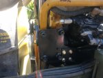
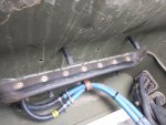
The cab unit required that I make a template and drill 4 holes - two for the AC fittings and two for the rear most evap drain tubes:
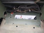
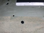
IMG_20220515_145738173.jpg
IMG_20220515_145743262.jpg
IMG_20220515_145745621.jpg

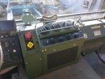
Fitment was excellent though and basically fits like it was designed to be there:


IMG_20220515_160108070.jpg
IMG_20220515_180927069.jpg

Notes:

1. You will need a helper. With the cab lowered you can access the front four bolts from the grill area (remove the grill), but someone needs to be on the inside to push the unit forward against the foam and so forth to get the bolts started.

2. The wiring in the back needs to be carefully zip tied away from the wiper linkage.

3. The brake controls will move up and back and all the lines to the controls will need to be replaced and extended by about 3.5-4" for push-connect fitting trucks. If you have the older ferrule connections then measure carefully. I was able to make the lines and route them through the maze of hoses and wiring on the bench - be careful to avoid the electric flapper actuators, sharp hose clamps, etc. On the C7 controls the exhaust vent is not routed to the bottom of the cab but instead has a sintered brass filter/muffler installed directly on the controls - this might be a useful mod for those with older trucks.

4. The floor HVAC hoses.... The driver's side can use the supplied adapter that twists into the box, but the passenger side required the use of the old adapter from the original heater box. Bending the tabs a bit and then crushing it slightly oval was all that it required. Reason being the proximity of the Transmission Control Module won't allow the longer adapters supplied with the new HVAC cab unit.

The condenser install was really straightforward. Had to drill two holes in the skid plate mounting brackets but otherwise it bolted right up with no modifications.

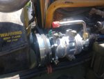
Onto the compressor:

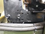
Ran into an issue with the bolt hole alignment on my reproduction compressor mounts:

IMG_20220520_185826930.jpg

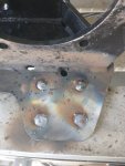
It appears the bolt holes were never going to line up - in the first place the lower/rear plate hits the compressor mounting boss long before the bolt holes line up anyway. And no the lower/rear plate can't go behind the front/upper plate - it's all wrong if you try that. So........

IMG_20220521_111003_01.jpg
IMG_20220521_114216617.jpg
IMG_20220521_130722322.jpg
IMG_20220521_142427026.jpg

Moved the holes and bolted it all up. Notes:

1. The air compressor coolant line had to be re-routed. Also added a cushioned loop clamp at the bottom of the timing gear case to push it up so it will not rub against the compressor bracket or other objects. It's tight.

2. The coolant tube from the fill tank is in the way of the AC belt tensioner. This required removing the cushion loop clamps from the transmission cooler, shoving the tube farther into the connecting hose on the engine side, and pushing it back behind the oil fill pipe. Note that this blocks the upper AC bracket/air compressor mounting bolt so that needs to be secured first.

3. The wiring harness must move forward of the air compressor coolant hose so it's between the oil fill pipe and the coolant hose. The cushion clamp got moved up one bolt hole position on the timing case.

It's all worked out so far. Just a LOT of modification for the compressor fitment. The rest is hose routing and some wiring hook ups. Should be relatively easy from here.
 
Last edited:

INFChief

Well-known member
722
1,348
93
Location
New York
I'm told by a MotorPool veteran of 20 years that "soft cab" trucks were basically never equipped with AC. He couldn't recall ever seeing one in fact. The A1P2 armored cab trucks all have it and in fact AC malfunction is a deadline. The AC only has to drop the ambient temp by 20 degrees F to be considered operational though (generally they work much better than this spec).

So far I've got the cab evap unit installed, the condenser core installed, and the compressor installed. Currently working on hoses and routing the last of the wiring.

The cab unit required that I make a template and drill 4 holes - two for the AC fittings and two for the rear most evap drain tubes:
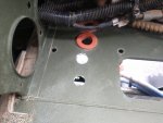
View attachment 868396
View attachment 868397
View attachment 868398

Fitment was excellent though and basically fits like it was designed to be there:

View attachment 868399
View attachment 868400

Notes:

1. You will need a helper. With the cab lowered you can access the front four bolts from the grill area (remove the grill), but someone needs to be on the inside to push the unit forward against the foam and so forth to get the bolts started.

2. The wiring in the back needs to be carefully zip tied away from the wiper linkage.

3. The brake controls will move up and back and all the lines to the controls will need to be replaced and extended by about 3.5-4" for push-connect fitting trucks. If you have the older ferrule connections then measure carefully. I was able to make the lines and route them through the maze of hoses and wiring on the bench - be careful to avoid the electric flapper actuators, sharp hose clamps, etc. On the C7 controls the exhaust vent is not routed to the bottom of the cab but instead has a sintered brass filter/muffler installed directly on the controls - this might be a useful mod for those with older trucks.

The condenser install was really straightforward. Had to drill two holes in the skid plate mounting brackets but otherwise it bolted right up with no modifications.

Onto the compressor:

Ran into an issue with the bolt hole alignment on my reproduction compressor mounts:

View attachment 868401

It appears the bolt holes were never going to line up - in the first place the lower/rear plate hits the compressor mounting boss long before the bolt holes line up anyway. And no the lower/rear plate can't go behind the front/upper plate - it's all wrong if you try that. So........

View attachment 868402
View attachment 868403
View attachment 868404
View attachment 868406

Moved the holes and bolted it all up. Notes:

1. The air compressor coolant line had to be re-routed. Also added a cushioned loop clamp at the bottom of the timing gear case to push it up so it will not rub against the compressor bracket or other objects. It's tight.

2. The coolant tube from the fill tank is in the way of the AC belt tensioner. This required removing the cushion loop clamps from the transmission cooler, shoving the tube farther into the connecting hose on the engine side, and pushing it back behind the oil fill pipe. Note that this blocks the upper AC bracket/air compressor mounting bolt so that needs to be secured first.

3. The wiring harness must move forward of the air compressor coolant hose so it's between the oil fill pipe and the coolant hose. The cushion clamp got moved up one bolt hole position on the timing case.

It's all worked out so far. Just a LOT of modification for the compressor fitment. The rest is hose routing and some wiring hook ups. Should be relatively easy from here.
Great progress! Thanks for posting all the things you encountered and how you worked around them. Looking forward to more updates!
 

INFChief

Well-known member
722
1,348
93
Location
New York
I'm told by a MotorPool veteran of 20 years that "soft cab" trucks were basically never equipped with AC. He couldn't recall ever seeing one in fact. The A1P2 armored cab trucks all have it and in fact AC malfunction is a deadline. The AC only has to drop the ambient temp by 20 degrees F to be considered operational though (generally they work much better than this spec).

So far I've got the cab evap unit installed, the condenser core installed, and the compressor installed. Currently working on hoses and routing the last of the wiring.

The cab unit required that I make a template and drill 4 holes - two for the AC fittings and two for the rear most evap drain tubes:

View attachment 868396
View attachment 868397
View attachment 868398

Fitment was excellent though and basically fits like it was designed to be there:

View attachment 868399
View attachment 868400

Notes:

1. You will need a helper. With the cab lowered you can access the front four bolts from the grill area (remove the grill), but someone needs to be on the inside to push the unit forward against the foam and so forth to get the bolts started.

2. The wiring in the back needs to be carefully zip tied away from the wiper linkage.

3. The brake controls will move up and back and all the lines to the controls will need to be replaced and extended by about 3.5-4" for push-connect fitting trucks. If you have the older ferrule connections then measure carefully. I was able to make the lines and route them through the maze of hoses and wiring on the bench - be careful to avoid the electric flapper actuators, sharp hose clamps, etc. On the C7 controls the exhaust vent is not routed to the bottom of the cab but instead has a sintered brass filter/muffler installed directly on the controls - this might be a useful mod for those with older trucks.

The condenser install was really straightforward. Had to drill two holes in the skid plate mounting brackets but otherwise it bolted right up with no modifications.

Onto the compressor:

Ran into an issue with the bolt hole alignment on my reproduction compressor mounts:
View attachment 868401

It appears the bolt holes were never going to line up - in the first place the lower/rear plate hits the compressor mounting boss long before the bolt holes line up anyway. And no the lower/rear plate can't go behind the front/upper plate - it's all wrong if you try that. So........
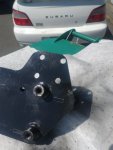
View attachment 868402
View attachment 868403
View attachment 868404
View attachment 868406

Moved the holes and bolted it all up. Notes:

1. The air compressor coolant line had to be re-routed. Also added a cushioned loop clamp at the bottom of the timing gear case to push it up so it will not rub against the compressor bracket or other objects. It's tight.

2. The coolant tube from the fill tank is in the way of the AC belt tensioner. This required removing the cushion loop clamps from the transmission cooler, shoving the tube farther into the connecting hose on the engine side, and pushing it back behind the oil fill pipe. Note that this blocks the upper AC bracket/air compressor mounting bolt so that needs to be secured first.

3. The wiring harness must move forward of the air compressor coolant hose so it's between the oil fill pipe and the coolant hose. The cushion clamp got moved up one bolt hole position on the timing case.

It's all worked out so far. Just a LOT of modification for the compressor fitment. The rest is hose routing and some wiring hook ups. Should be relatively easy from here.
Was this mostly a kit of things you pulled together?
 

GeneralDisorder

Well-known member
Steel Soldiers Supporter
2,036
5,224
113
Location
Portland, OR
Yeah, I've been stalking his website for months. Thanks.
I ordered back in November and it took about 5 weeks for all of it to come in. I would contact him and get an order started since he has them made in batches and many are spoken for before the web site gets updated with stock.

He is the only supplier I have seen with the actual mil-spec condenser cores. And his pricing is good - was better last year but everything has gone up with the cost of freight, etc.
 

Guruman

Not so new member
Steel Soldiers Supporter
I ordered back in November and it took about 5 weeks for all of it to come in. I would contact him and get an order started since he has them made in batches and many are spoken for before the web site gets updated with stock.

He is the only supplier I have seen with the actual mil-spec condenser cores. And his pricing is good - was better last year but everything has gone up with the cost of freight, etc.
I see the the compressor kits are back on his website. I ordered the rest of the things I need to get this project going. It's getting pretty hot around here. My trip to pickup my box was a sweaty one.

I'll end up with more bits than I need since I ordered the whole compressor kit but already had the compressor and pulley.
I'm not looking forward to all this work, but I am anxious to get some A/C.

Next I need to tackle those highway gears.....
 

INFChief

Well-known member
722
1,348
93
Location
New York
I see the the compressor kits are back on his website. I ordered the rest of the things I need to get this project going. It's getting pretty hot around here. My trip to pickup my box was a sweaty one.

I'll end up with more bits than I need since I ordered the whole compressor kit but already had the compressor and pulley.
I'm not looking forward to all this work, but I am anxious to get some A/C.

Next I need to tackle those highway gears.....
Do you need to install a second pulley on the crank? Am very curious as to how your install goes! Please keep us updated.
 

Guruman

Not so new member
Steel Soldiers Supporter
Do you need to install a second pulley on the crank? Am very curious as to how your install goes! Please keep us updated.
Yes. It's my understanding that you have to install a second pulley between the fan and crank. At least for my A0 and it's 3116 engine. I got one from my local CAT dealer, but the compressor kit comes with one as well. many of the available YouTube vids show installing the pulley by separating the fan clutch from the crank.

I think this is true for the 3126 as well, but the C7 engines, I believe, are serpentine belts, so those are likely a different setup.... maybe.


1653590065293.png

Here's the best pic I could search up showing the A/C belt layout, but it's missing the passenger side belt routing, so I'm not exactly sure how it goes, but I'll find out once I get into it, I suppose. I think the passenger side accessory drive is behind the large painted balancer, closer to the engine block.
 

GeneralDisorder

Well-known member
Steel Soldiers Supporter
2,036
5,224
113
Location
Portland, OR
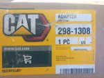
The C7 is identical to the 3116 and 3126 as regards the crank adapter and the compressor brackets, etc. I installed a new fan (yellowed blades from the desert) and a new fan clutch when I installed the belt pulley. It replaces a blank spacer that is between the balancer and the fan clutch. This is the part from CAT:

IMG_20220526_153937110.jpg

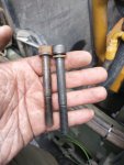
You will need 10mm x 1.5 x 85mm socket head bolts to replace the ones that come out. It does push the fan about 9mm closer to the radiator.

IMG_20220507_164251015.jpg

Here it is completely installed with new fan, fan clutch, and belt pulley:

IMG_20220507_174330899.jpg

One thing to note - the fan clutch is air released. It is not likely the driven side will align with the drive side for removal of the mounting bolts. You will want to have compressed air handy to release the clutch and spin the fan (driven) end so the access holes line up with the bolt heads.
 
Last edited:

GeneralDisorder

Well-known member
Steel Soldiers Supporter
2,036
5,224
113
Location
Portland, OR
I see the the compressor kits are back on his website. I ordered the rest of the things I need to get this project going. It's getting pretty hot around here. My trip to pickup my box was a sweaty one.

I'll end up with more bits than I need since I ordered the whole compressor kit but already had the compressor and pulley.
I'm not looking forward to all this work, but I am anxious to get some A/C.

Next I need to tackle those highway gears.....
It is definitely a bit of work. I have about 2 full days on the install spread out over a couple weeks as I have time. I would say the labor broke down about like this:

1. Fan, fan clutch, pulley installation. Includes dropping the lower fan shroud to remove the upper fan shroud, intercooler pipe, etc: 4 hours.
2. Condenser core install - R&R skid plate, drill holes in skid plate mounts, etc: 2 hours.
3. Cab unit (evap/heater core install). You will need some assistance from a friend..... 6 hours.
4. Compressor brackets and modifications needed as in my original post. 5 hours.

I haven't tackled running the hoses, charging it, and some of the wiring yet. So I would say if you are planning on this job figure an entire weekend and possibly a three day weekend at that.
 

GENX

Active member
129
218
43
Location
TX
I ordered back in November and it took about 5 weeks for all of it to come in. I would contact him and get an order started since he has them made in batches and many are spoken for before the web site gets updated with stock.

He is the only supplier I have seen with the actual mil-spec condenser cores. And his pricing is good - was better last year but everything has gone up with the cost of freight, etc.
Did you get a condenser with the two spall fans?
 

GENX

Active member
129
218
43
Location
TX
I was looking at those, can they be submerged?
You going to add a switch to turn them off during water fording, maybe slaved to a relay off the fan cutoff switch ?
 
Last edited:

GeneralDisorder

Well-known member
Steel Soldiers Supporter
2,036
5,224
113
Location
Portland, OR
Due to the components and hoses I'm using I need to switch over to a different trinary switch. The one Tom is using in his wiring kits is a bit of an odd unit - being a factory switch for a 2001 to 2006 Hyundai Santa-Fe (the only application I could find anyway) and there is basically NO wiring information on the internet for this unit. Further complicating matters the wiring harness he supplies doesn't come with a diagram and three of the four wires to the switch are the same color (3 black and 1 yellow) which is not "convention" in the trinary switch aftermarket (green/black for compressor clutch, and blue for fan).

I am going to use a standard trinary switch - more readily available and also threads onto a shader port on the drier I'm using so it can be changed without discharging the system (much) should the need arise. It also has the correct wire colors that make troubleshooting easier.

Luckily I have access to Mitchel and was able to track down the pinout and pressure settings of this unit. I'm posting them here in case anyone needs this information for replacement or troubleshooting. Just knowing the pinout can enable you to jumper this switch out in case of failure or for diagnostic purposes.

The switch specs are: HPCO: 455 psi, HPCI: 370 psi. LPCO: 28 psi, LPCI: 33 psi. Fan On: 250 psi, Fan Off: 200 psi

Waterloo Trinary Switch Diagram 1.jpg

Waterloo Trinary Switch Diagram 2.jpg
 
Last edited:
Top
AdBlock Detected

We get it, advertisements are annoying!

Sure, ad-blocking software does a great job at blocking ads, but it also blocks useful features of our website like our supporting vendors. Their ads help keep Steel Soldiers going. Please consider disabling your ad blockers for the site. Thanks!

I've Disabled AdBlock
No Thanks