• Steel Soldiers now has a few new forums, read more about it at: New Munitions Forums!

  • Microsoft MSN, Live, Hotmail, Outlook email users may not be receiving emails. We are working to resolve this issue. Please add support@steelsoldiers.com to your trusted contacts.

Glow plug card

Terracoma

Member
334
14
18
Location
Albuquerque, NM
View attachment 740277

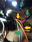
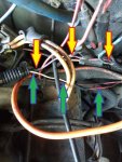
You mean this bundle here? Looks the same, except this plug is routed up around the top of the instrument clutser. I unplugged it and turned the key on, and the glow plug system still functioned, which correct me if I'm wrong but shouldn't the glow plugs not be able to cycle with the card unplugged?
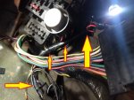
Negative, I don't think that's the correct connector/bundle, but I'm diving into the wiring TM's right now to verify the wire colors.

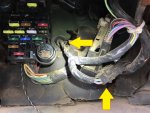
I've taken your photo and added some colored arrows to highlight the harness that we're looking for. Largest arrow at right should be where the grommet goes thru the firewall. Smaller arrows are the harness, and it looks like the connector at the very bottom of your photo (other large arrow) is disconnected. This is the harness we're chasing.


Oerthedge21_01.jpg
 
Last edited:

Oerthedge21

Member
250
20
18
Location
Northford CT
The one at the bottom, with the square plug connector is in fact connected to it's other half, just doesn't look like it in the photo. However, something else here isn't right. I had pulled the dash off to see up on top of it to try and follow some wires and clean up a few poorly done connections, when I found the wts light had been screwed with also. The pink/black wire that feed power to the bulb has been cut and spliced into a pink/white wire that goes somewhere I haven't found yet. I tested the other side of the pinkblack wire and found that when the key is turned that wire is getting power continually, not shutting off after the relay clicks. The pink/white one does shut down after the relay click, so something else isn't right either
 

Terracoma

Member
334
14
18
Location
Albuquerque, NM
I agree with your assessment, someone has definitely messed with your wiring.

The WTS light bulb should be fed by a pink wire with a black tracer (pink/black) and grounded through a dark blue wire that is controlled by the glow plug card. This dark blue wire should backtrack through the main harness (behind the gauge cluster) and down to that small 4-wire connector that we're talking about (that appears disconnected, but isn't)... The other end of this small connector joins up with the glow plug harness.


The "other end" of the 4-pin connector shown at the bottom of my photo here, for clarity. Upper arrow shows the firewall grommet. Just to the right of the upper arrow is my glow plug card controller box and wiring (secured with a white zip tie), and you can see the harness is Y-split between the firewall grommet and the 4-pin connector.

M1008_GP_Wiring_02.jpg
 
Last edited:

Oerthedge21

Member
250
20
18
Location
Northford CT
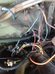
IMG_20180903_133422133_LL.jpgIMG_20180903_133433342_LL.jpg
Oh man the further I go the worse it gets. I'm not sure how this system functioned at all honestly, looks like I might have to rewire the whole system, or is it savable somehow?
 

Oerthedge21

Member
250
20
18
Location
Northford CT
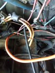
IMG_20180903_135216837.jpgIMG_20180903_135247533.jpg
As you can see some of the underhood wiring isn't right either, I don't know what the circular plug is that's just sitting there, but that civy stlye gp controller doesn't seem to be there so I'm not sure where the controller had been run to in this case. There's multiple wires spliced into different colors, two of which are in the second pic, kinda hard to see
 

firefox

General
Steel Soldiers Supporter
1,845
51
48
Location
Berkeley CA
I stand corrected about the two little boxes.I now know there are supposed to be three and the third is larger. Sorry if this wasted your time.
 

Terracoma

Member
334
14
18
Location
Albuquerque, NM
Follow the pink/black wire in this photo on the engine side of the firewall. Where does it go? It should go to glow plug relay.

Also, the purple/white wire that is spliced with electrical tape with a red wire at the top right of this photo...the red wire goes around the grommet and thru the firewall to the engine side...Where does it go? It should go to a glow plug controller, as the purple/white wire is the "after glow" signal wire, and normally goes to the military glow plug controller card on the cab side of the firewall.


Oh man the further I go the worse it gets. I'm not sure how this system functioned at all honestly, looks like I might have to rewire the whole system, or is it savable somehow?
It's looking like someone removed your military-style glow plug card controller and might have installed a civilian-style controller on the engine side of the firewall. This is a common modification when a military GP system is misbehaving and someone doesn't want to troubleshoot the system...


EDIT: In light of your engine side photos, you have a civilian glow plug controller and your wiring has been modified as such.
 

Oerthedge21

Member
250
20
18
Location
Northford CT
Follow the pink/black wire in this photo on the engine side of the firewall. Where does it go? It should go to glow plug relay.

Also, the purple/white wire that is spliced with electrical tape with a red wire at the top right of this photo...the red wire goes around the grommet and thru the firewall to the engine side...Where does it go? It should go to a glow plug controller, as the purple/white wire is the "after glow" signal wire, and normally goes to the military glow plug controller card on the cab side of the firewall.


It's looking like someone removed your military-style glow plug card controller and might have installed a civilian-style controller on the engine side of the firewall. This is a common modification when a military GP system is misbehaving and someone doesn't want to troubleshoot the system...


EDIT: In light of your engine side photos, you have a civilian glow plug controller and your wiring has been modified as such.
Well that would explain the mess and MIA gp controller. So that thing down in the head is actually the controller? I thought it was the temp sensor, considering the civilian controller went in the driver's side head (correct me if I'm wrong) and the temp sensor was positioned in the pass side head.
 

Terracoma

Member
334
14
18
Location
Albuquerque, NM
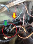
Correct, that gray unit that has the large-gauge orange wires attached is a 2-in-1 unit: it's both your glow plug controller AND your glow plug relay.


EDIT: The red circle is the controller/relay, the red and yellow arrow is your 12v power wire that's feeding the glow plug relay, and the blue and green arrow is the controller wiring that is running back thru the firewall into the cab of the truck.

It's worth noting that your glow plugs have been converted to 12v, and I believe the wiring from the 12v block to the relay is undersized for the current draw of all eight glow plugs. Beware, as this could be a fire hazard.


Oerthedge21_02.jpg
 

Oerthedge21

Member
250
20
18
Location
Northford CT
Ohhhh ok that would make more sense. Man I don't like that at all. Never would've figured it out without you guys though, thank God for this forum. Guess for now I'll just have to run this system then, thank you all for the help
 

Terracoma

Member
334
14
18
Location
Albuquerque, NM
I'm not familiar with how the civilian GP controllers work, unfortunately, so I'm not much help there. For what it's worth, based on your photos, it doesn't look like you're too far off from the original military wiring...you could return it to the stock setup, if you were inclined to do so, and it would remove a fair amount of butchered and dead-end wiring.

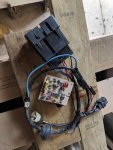
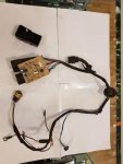
You'd need an uncut glow plug controller harness (like the two photos below, which I found on eBay), the correct glow plug relay, the correct glow plug temp sensor, and beef up the feed wiring to/from the new relay. You'd be able to use that new controller card that you purchased, and future troubleshooting will be easier, especially with the Technical Manuals matching your wiring... The only downside will be cost, as everything CUCV-related is worth it's weight in gold nowadays.

[thumbzup]


GPwiring02.jpg GPwiring01.jpg
 

Oerthedge21

Member
250
20
18
Location
Northford CT
I think I might do that, that system looks far simpler than the crap that's currently rigged in there. And it'd be a shame to just let that 110$ card collect dust. I guess I'll have to start finding parts then.
 

Terracoma

Member
334
14
18
Location
Albuquerque, NM
In terms of complexity, I'd actually say the military control system is more convoluted than the civilian controller, as there's less wiring required to run the newer civilian controllers like you have installed... Whoever did the conversion on your truck simply did a sloppy job, and wasn't thorough about cleaning up the wiring.

After reviewing the below schematic for the civilian controller, it looks the purple/white wire under your dash that's been spliced to the red wire (blue/green arrow) is connecting to the "B" terminal on your controller? If so, this wire signals the controller that you're cranking the engine. The pink/black wire (red/yellow arrow) has been spliced several times to reach the "D" terminal on your controller. This wire is "ignition hot" and signals the controller that the ignition switch is in the "run" position.

I can't be certain without seeing more photos, unfortunately... That purple/white wire could also be a 12v feed to the starter relay, and my blue/green arrows are incorrect. You never mentioned if this M1010 is still 12v/24v or converted to straight 12v.


Civi_GP_Controller.jpg Civi_GP_Wiring01.jpg Civi_GP_Wiring02.jpg


You could keep this setup if it works for you, just repair everything that's iffy and remove all the unnecessary wiring...but in the end, it's up to you to decide if the simplicity is more important than originality.
 

Oerthedge21

Member
250
20
18
Location
Northford CT
Oh yes my apologies, it's been somewhat converted to 12v, one alt was pulled, batteries were rewired. Again a somewhat poorly done job but it works so I haven't dug into it yet
 
Top