- 259
- 274
- 63
- Location
- Grove, Oklahoma
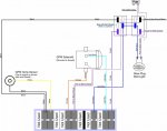
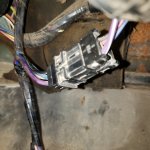
Hello All... I have been working on trying to fix the Glow Plug system in my M1009. Thanks to the sticky notes and other information in the helpful threads, I think I was able to isolate what I believe is the primary problem. Coming from the GP Module Housing, I noticed that the wires split into two paths. One path goes out into the engine compartment while the other path goes into a 6 pin connection. Within this 6 pin connection only 4 1/2 of the pins are used. I say 4 1/2 because on one side of connector there are 5 wired pins (one of which is Blue w/ Red Chaser that goes into the engine compartment and stops). On the other side of the 6 pin connector there are four wired connectors (there is no mating connection for the Blue w/ Red Chaser wire). These wires quickly disappear into the wiring harness. I chose to call this side of the 6 pin connector "Truck Side".
The four wires on the "Truck Side" of the connector are: Black, Pink w/ Black Chaser, Dark Blue and Purple w/ White Chaser.
Black goes to Ground - Verified with my meter set to continuity.
Dark Blue goes to Glow Plug Wait Light - Verified with my meter set to continuity.
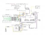
Purple w/ White Chaser goes to Ignition Switch (Not Verified - Information gained from image provided in Sticky Notes)
Pink w/ Black Chaser goes to two places. Place #1 = Glow Plug Wait Light, Place #2 = 12V FUSED Power source when the key is in the RUN position (as depicted on the schematic).
In my case, I do not have power to the pink w/ black chaser wire when the key is turned to the RUN position. According to the schematic, this wire gets it power from a fuse. I determined that this wire (and perhaps the fuse) is only energized when the key is in the RUN position by using my test light on my FMC M1008.
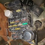
How do I determine which fuse is supposed to be the power source for the Glow Plug Module? As best that I can tell, every fuse in my block is a good fuse. I tested each one with my meter set on continuity.
If all of the fuses are "Good", then the problem could be between the fuse block and "Truck Side" of the six pin connector and/or the wait light, however, it could also be a disconnect between the ignition switch and the fuse block which would prevent the fuse (whichever one) from being energized when the key is turned to the RUN position.
Thoughts anyone???


