• Steel Soldiers now has a few new forums, read more about it at: New Munitions Forums!

  • Microsoft MSN, Live, Hotmail, Outlook email users may not be receiving emails. We are working to resolve this issue. Please add support@steelsoldiers.com to your trusted contacts.

Glow plug relay output voltage & manual button hold duration

KallyLC

Active member
78
146
33
Location
Atherstone, UK
So, bit of backstory. Had a crank/no start issue on my 1008, wasn't even attempting to fire. Little bit of diagnosis later and we realize it's not getting any voltage to the glow plugs, even though the relay was getting 12v in, was clicking on and off as it should and the WAIT light was operating.

Replaced the relay, still having problems. The troubleshooting I did with it on the vehicle seemed to indicate it was the relay that was the problem, but I tested it later with a 12v power supply and it works fine. The WAIT light stopped working entirely now.

So it's not the relay, seems like the glow plug card is toast. Wired up a manual glow plug button for testing purposes between a 12v source and the blue wire on the relay, and that does work, although the output side of the relay is only giving 10v. Never measured it while it was working fine, so I'm not sure if this is normal? Despite that, the manual switch did successfully start it, but it took two attempts and probably required longer on the glow plugs as it had a hard time getting going.

The manual button started as a test method, but as much as I'd like to keep things original, the replacement cards aren't cheap, and the manual switch seems like it removes the potential for future failure entirely, so I'm planning on installing it as a permanent fixture.

I am still a novice to diesels so without the WAIT light I'm flying a bit blind, I never thought to actually time the duration the WAIT light stayed on for whilst it was working and my guess of 10-15 seconds seems as if it was a bit optimistic. It was about 45-50F today, so I'd be interested to know what the norm for these kinds of conditions are, and how long you can safely activate the glow plugs for without risking damage. I've seen from 10-25 seconds mentioned reading through other threads but I'm not sure of the temperature ranges those were for.
 

MarcusOReallyus

Well-known member
4,524
816
113
Location
Virginia
Measure the difference between the input and output of the relay while the GPs are engaged, i.e., the relay is ON. Should be zero difference. (And here I just wondered about the value of that test on another thread..... :D ) If you are dropping a couple of volts across that relay, toss it!


The blue wire should be grounded to engage the relay. The small pink (redish) wire should have 12v.

Do you have the original GP resistor in place? OR has it been bypassed? If you are not sure, meaure the voltage at the INPUT (large red wire, usually at the top of the relay) when the relay is NOT engaged (GPs are OFF). If it's 12-ish volts, your resistor has been bypassed. If it's 24-ish, it it still in place.

A pretty pictoor of your GP wiring would help us sort this out.
 

antennaclimber

Moderator
Moderator
Steel Soldiers Supporter
1,368
950
113
Location
State College, PA
The GP card has a couple of variable inputs that determine the duration of the glow plug heating time.

The colder the engine is, the longer it keeps the Wait light on, the warmer the engine is, the shorter the wait duration.

The GP card also provides the after glow heating of the glow plugs if it is necessary based on the variables sent to it.

There is no set time that the card provides, the duration of the wait and heat times are based on engine temperature, voltage to glow plugs and voltage.

Best guess, when the engine hot, no heat may be needed, warm, 5-15 seconds, cold, 10-20 seconds, extreme cold, 20 seconds or more.
I have heat times as long as 45 to 60 seconds in very cold conditions.

Like Marcus suggested, check the relay voltage on the two large terminals, they should be the same.
This happened to my GP relay:
Relay Failure
 

KallyLC

Active member
78
146
33
Location
Atherstone, UK
Measure the difference between the input and output of the relay while the GPs are engaged, i.e., the relay is ON. Should be zero difference. (And here I just wondered about the value of that test on another thread..... :D ) If you are dropping a couple of volts across that relay, toss it!


The blue wire should be grounded to engage the relay. The small pink (redish) wire should have 12v.

Do you have the original GP resistor in place? OR has it been bypassed? If you are not sure, meaure the voltage at the INPUT (large red wire, usually at the top of the relay) when the relay is NOT engaged (GPs are OFF). If it's 12-ish volts, your resistor has been bypassed. If it's 24-ish, it it still in place.

A pretty pictoor of your GP wiring would help us sort this out.
As mentioned above, I'm getting about 10v out of the new relay with it engaged. The old one was putting out 0v. The resistor block has been bypassed and the relay is being supplied 12v.

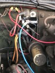
This is the TEMPORARY switch installation we were using to test and troubleshoot, don't crucify me. The two additional wires go to a starter switch over by the
brake master.
IMG_2651.JPG


I am now realizing that this switch installation, even though it works, is wrong, as it's set up to supply 12v to the blue wire instead of linking it to a ground. I will have to look at correcting that, and it might explain some of the issues we were having. I'm not sure if it's why the voltage is only 10v but it's likely not helping.

The relay that was on there to start with was visually identical to the current one, so it had already been replaced at some point before.

I feel a bit of a moron but i'm struggling with a hodgepodge of someone else's wiring combined with a system I'm still learning about. It's possible wiring it up incorrectly killed the glow plug card, but the fact that the original relay tests fine with a 12v power source suggets that the relay was never the problem to start with.
 

antennaclimber

Moderator
Moderator
Steel Soldiers Supporter
1,368
950
113
Location
State College, PA
Kally,
No offense or other demeaning connotations intended on my part. My apologies if I sound harsh.

This may help you understand the GP system:
GP Module Theory of Operation

Keep asking questions and we will help get your GP system working. Figuring out other peoples wiring can be difficult.
 

MarcusOReallyus

Well-known member
4,524
816
113
Location
Virginia
As mentioned above, I'm getting about 10v out of the new relay with it engaged.
Thet ain't raht, but see below.

This is the TEMPORARY switch installation we were using to test and troubleshoot, don't crucify me. The two additional wires go to a starter switch over by the brake master.
All is forgiven! :D

I am now realizing that this switch installation, even though it works, is wrong, as it's set up to supply 12v to the blue wire instead of linking it to a ground. I will have to look at correcting that, and it might explain some of the issues we were having.
Yeah, that is very weird. I have to wonder if you have the correct relay. Check for continuity from any of the terminals to ground. There should NOT be any. You must use an isolated ground relay. See the sticky for the correct relay.

I feel a bit of a moron but i'm struggling with a hodgepodge of someone else's wiring combined with a system I'm still learning about.
Hey, cleaning up someone else's mess is a tough job. No need to feel like a moron.


It's possible wiring it up incorrectly killed the glow plug card,


Possible, but let's get that relay checked before jumping to any conclusions. Sumpin' ain't raht here. Would you humor me and test the voltage across the two LARGE terminals of the relay when the GPs are heating? It should read zero. I have me a suspicion but I don't want to say anything until I see that number.
 

KallyLC

Active member
78
146
33
Location
Atherstone, UK
Well it turns out that we assumed wrong, the seemingly identical relay we bought to replace the 'broken' old one is NOT the same. It turns out that the relay we removed was an isolated ground unit, and it has 0 resistance whilst active so it seems to be absolutely fine.

The replacement that grounds to the firewall is working just fine for the time being. Since we put in a more permanent, heavier-duty manual switch at the weekend the output has jumped up to 12v with 0 resistance, so I'm not sure if the 10v was a bad measurement or what.

I am going to put the original unit back in, and I have ordered a new glow plug controller card from hillbilly wizard. Seeing as all my glow plugs are fine and the relay was never broken to begin with, the controller card is the only culprit left.

It's been a useful learning experience, electronics are not my area of expertise but I now know a lot more than I did a week ago.
 
Last edited:

Curtisje

Well-known member
Steel Soldiers Supporter
596
693
93
Location
Okinawa, Japan
I cannot remember where I read it but the wait light should light for either 11 or 13 seconds. So I hold my button for 13 seconds in the morning... 14 if it's real cold.

Not sure if you were still interested in the times or not. Good luck.
 

Guruman

Not so new member
Steel Soldiers Supporter
I seem to remember something from 20 years ago about older style glow plugs swelling if left on too long making them difficult to remove.

It seems to me the recommendation was to use a newer style that "self limited" maybe?

Anyway, I might be wrong, it's been a long time, but it might be worth some research for anyone considering a manual glow plug switch. Just thought I'd mention it.
 

KallyLC

Active member
78
146
33
Location
Atherstone, UK
I'll be using the manual button for a little while untill my new card turns up, so it's still good to know how long it needs, thanks.

I removed all the glow plugs to test and inspect them last weekend and they all seem to be fine, I was concerned they might be swollen and a pain to remove but they came out no problem.
 

MarcusOReallyus

Well-known member
4,524
816
113
Location
Virginia
Well it turns out that we assumed wrong, the seemingly identical relay we bought to replace the 'broken' old one is NOT the same.

I suspected that. They look the same.


The replacement that grounds to the firewall is working just fine for the time being.
If you want to fry your new controller card, leave that grounded relay in there.


Glad you got it figured out! :beer:
 

Michael

Active member
1,348
24
38
Location
Fulton, MS
I spent the afternoon getting mine running again. Eight working glow plugs is a heavy load. I measured about 10.5 volts at the relay that increased past 11 as they heated up. My problem turned out to be the part the relay moves in the injection pump was stuck. My battery is getting old, but if you don't see a significant voltage drop at the relay output when it is engaged I would be checking for burnt out plugs. I didn't see much difference between input and output voltage.
 

KallyLC

Active member
78
146
33
Location
Atherstone, UK
I think the low voltage output I originally spoke of might have been just a bad reading, as I wasn't able to get it to happen again when I tested it the second time. I'll do some more testing when I put the original relay back in and install the new card today.

I tested all my glow plugs as part of the troubleshooting , and they were all well within spec.
 

KallyLC

Active member
78
146
33
Location
Atherstone, UK
To cut a very long story short and gloss over a lot of rookie troubleshooting efforts, we put the original 'good' relay back in, and installed the new GP control card. It didn't fix it.

Now armed with slightly more of an idea of what we were doing than the first time, we re-tested the original relay and found out that it was in fact, definitely dead. It was going click, but the power still wasn't getting through it.

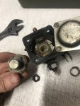
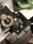
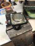
I was curious, so I drilled out the rivets to take a look inside and find out how it worked before I ordered a replacement, and it turned out to be fairly obvious why it had stopped working. The contacts were black. I cleaned it up and bolted it back together, and it's working as good as new. I'd planned this as a temporary fix but it's working fine so I may stick with it a while and see how it goes. I managed to avoid destroying the cardboard gasket for the top cover, but it's still maybe not as sealed up as it used to be.

If it gunks up again I can just give it another clean or replace it now I've found a place that stocks the tin can type solenoids in the UK.

IMG_2744.JPGIMG_2748.JPGIMG_2751.JPG

I don't know whether i'm relieved or annoyed that it ended up being this simple of a fix after all the head scratching. At least it's been educational.
 
Top
AdBlock Detected

We get it, advertisements are annoying!

Sure, ad-blocking software does a great job at blocking ads, but it also blocks useful features of our website like our supporting vendors. Their ads help keep Steel Soldiers going. Please consider disabling your ad blockers for the site. Thanks!

I've Disabled AdBlock
No Thanks