• Steel Soldiers now has a few new forums, read more about it at: New Munitions Forums!

  • Microsoft MSN, Live, Hotmail, Outlook email users may not be receiving emails. We are working to resolve this issue. Please add support@steelsoldiers.com to your trusted contacts.

Got my 803A with LTT-HC Trailer - Mods, Questions, and whatnot....

MixManSC

Member
35
77
18
Location
Columbia SC
So I have a lot to post about this. Hopefully some might find some of it useful. I also likely will have a few questions but honestly with the vast amount of info here on these forums I actually cannot really think of much as I actually know how to search on forums and read first. Crazy right.... ;)

Anyways I've already done of a ton of things but first part is what I have.
2003 803A with 20 hours - bought from a member of the local MVCC for considerably less than they go for on that auction site... He was kind enough to check it over, install two new batteries, and gave me a spare fuel filter, oil filter, and water separator. Handy to have those off the shelf part numbers.
It came on an 2010 Schutt LTT-HC 1-1/2 ton trailer. It is now mounted with the control panel at the rear. Manuals are still sealed and in the side box as well as a "Depreservation Guide". Did have the ground rod, ground wire, big plastic wrench still tied in, aux fuel hose.

Short list of mods so far in no particular order....
  • Replaced both of the leaky fuel tank rubber well nuts with brass ones.
  • Replaced the vast majority of the external rusting screws with new stainless ones. My God there are a LOT of them. Probably 10% of the originals broke off.
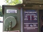
  • Flipped the extremely faded fault indicator panel over and painted new graphics on the back side. (I posted a vector artwork PDF in the documents section if anyone wants to do that.
  • Fuse mod had not been done. I did that, and went further and replaced the 400v diodes inside the VRM with 1000v ones for additional assurance that will never be an issue.
  • Coated all of the faded paint with Penetrol to darken it back up and bring the color back.
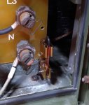
  • Added a switch to the control panel that is tied to the circuit breaker inside to make it more significant other friendly (she is not going to want to open the panel, just getting her to open the side to flips the dead crank switch is enough). Also added a military nuclear indicator light to come in with that switch for S&G.
  • Grabbed a full Pulse Tech kit that has the 12v/24v circuit breaker box, solar panel, battery charge state push button box on eBay (auction and got it for $65 for the whole kit. I'll have to do a full reply later on how I utilized that.
  • Converted the trailer tail lights to 12v (all markers were led so already 12v ready) and replaced the 12 pin connector with a consumer 7 pin one.
  • Replaced all of the fuel return line.
  • Bought a correct style slide hammer for the ground rod since that was missing.
  • Added aluminum screening to the side air intake vents and the bottom vent as we have a LOT of dirt daubers as well as field mice which love that sort of thing. I did not do anything with the top vent yet - still debating on that one. Thinking on just making a flip up cover for it that can flip over the back end when in use but on top to keep leaves, etc out when not in use.
  • Picked up an M60 AP distribution box with the 100' main big cable and one of the shorter 50' smaller cables for the cables and parts I wanted. Mounted the female from the box to the gen wiring output hole, male to my breaker panel to a 60A breaker and added an interlock kit. There are some gotchas I discovered with that bit of kit I'll get into later...

Future plans -
Going to have an expert welder buddy make a full custom aluminum belly tank for the trailer sitting above the axle and going up between the framing for greatly extended runtime. Hoping to get close to 125 gallons or more. We will pull the gen off, pull the axle, flip it over and figure it out. Should be fun. Part of that will also be including a fuel transfer pump to make filling out small tractor much easier and using it in that manner will also help to keep the fuel fresh as well as filling it up much easier (just tow it to the local station),

Getting some smaller stock plain steel GM wheels so I can put some smaller (and easier to replace) tires on it to lower it down to a somewhat more reasonable height for towing with a typical 4WD pickup. I have an H2 that is lifted with 37's - that does happen to tow it perfectly level but in the long run I do not plan on keeping the H2. Even if I put 31" tires on it, the lounge height is still going to be pretty high for the typical pickup but will at least be considerably better than it is now.

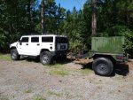
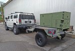
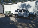
Anyways - pic of it behind my H2.... Hopefully most here know a bit about the H2. While far from an HMMWV the common public conception that it is a Suburban with a different body is far from reality as the H2 was built by AMG under contract right next to the H1. I can elaborate more if someone wants (the little H3 is however a just a Trailblazer with a different body).
IMG_20210521_165446222a.jpg
 

MixManSC

Member
35
77
18
Location
Columbia SC
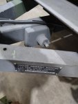
Oddly my first real question is in regards to the trailer. There is little info on it other than the standard docs which are from the 90's since they are still "mostly" the same. Mine has one fitting that I have not really explored yet. It is obvious someone has tried to turn it with something though.

Whatizzit??

IMG_20210529_152842204.jpg
 

MixManSC

Member
35
77
18
Location
Columbia SC
And..... remembering more mods.

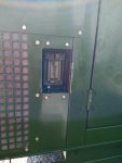
Removed the side NATO slave connector (I have no use for that) and added a 120V 20A GFCI duplex receptacle there.
Removed the fuel line storage box from the one lid and added a Square D QO breaker panel behind that lid.
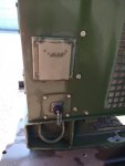
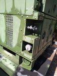
Added a 50A receptacle on the right side as well as a circular connector from the M60 dist box. That can connect another duplex 20A GFCI receptacle on the end of the 50' cable that came with the M60 box.
Replaced the ground tie bar with a knife switch to make it much easier to change from bonded to unbonded grounding (depending on if I am just connecting it to my house panel unbonded or using it in the field where it will be earth grounded and bonded).

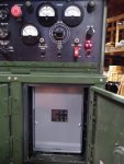
In this shot you can see the toggle switch I added the the circuit breaker wiring as well as the nuclear radiation indicator. No idea what that indicator came from, it is military and the exact same mounting as the panel lights. You can rotate the front lens to block the light off too. Have had a couple of them for many years. Can also see the QO breaker panel. The breakers are for the external receptacles I added. The panel is hard wired to the back side lugs of the wiring panel on the left side.

IMG_20210630_112047886.jpg
 

Zed254

Well-known member
866
466
63
Location
S. Hampton Roads, VA
Oddly my first real question is in regards to the trailer. There is little info on it other than the standard docs which are from the 90's since they are still "mostly" the same. Mine has one fitting that I have not really explored yet. It is obvious someone has tried to turn it with something though.

Whatizzit??

View attachment 839250
Jack Pad. Note curvature of the top shaft. This fits under the trailer axle. The pan (against trailer frame) fits over the top of the jack. Should be described in the trailer's TM.
 

MixManSC

Member
35
77
18
Location
Columbia SC
Some more info on the PCMDS charging setup.... Someone on here has posted the TM for the PCMDS kit before but if needed I can scan the copy that came with the one I bought.

These are intended for wheeled vehicles like the HMMWV which have a use for additional 24v and 12v circuits in addition to battery maintenance. This kit includes a 9” x 11” 28 volt, 200ma solar panel, a PTT (push to test) box which has 4 LED’s and a push button which will let you know the current charge level of the batteries, the PDB (pulsing distribution box – more on this next), and the needed cables, bolts, etc. I’ve seen a good number of these but more often lately it is just the PDB part. I found someone had the complete kit on eBay for auction and I ended up getting a great price on it.

This PDB part is a heavy plastic box with a watertight lid, a lot of wires coming out. What I found on getting it is that the box is extremely heavy duty and high quality. The wires all coming out are very high quality, highly flexible (pure copper) locomotive wire. On opening the box you are presented with an off the shelf Bussmann fuse panel mounted inside. This bugger is not easy to get apart for one. The wires all exit a large hole bored into one end through a cable retention fitting and all of the wires and the fitting are all just filled with silicone to make it supposedly water tight. To get it apart there are 4 screws and it then takes quite a bit of wrangling with the wires to get them separated and loose so that you can eventually get the fuse block tilted up enough to start getting it out of the case. What you will find is buried underneath the fuse block is the actual Pulse Tech charger that will also come out. That is really the only part I wanted…. The charger in these is non marked and 100% potted/sealed. It has a thicker cable that goes to a 4 pin connector which connects to the PTT module, a 2 pin wire that goes to an LED they drilled into the fuse block, then a 24vdc positive and negative wire which connected to the 24v part of the fuse block and a ground. They also include a nice Weather Pak connector for cutting/splicing the wire for the solar panel which I did use so that the main top cover can be removed with the solar panel still attached.

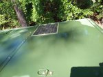
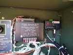
Since I really have no need to all these extra 24v and 12v circuits I just wanted the charging module from that part of the kit. How I installed it….. Solar panel is mounted on top above the connection space behind the main control panel box, drilled a hole, added a grommet, and ran the wire down, then through another hole into the control panel box. I mounted the PTT box inside the control panel box to the right of the VRM and using industrial hard plastic Velcro mounted the charge controller on top of the VRM. Then I drilled a hole to the right of the diagnostic connector for the LED. So far it works great. I also ran a 12awg pair of wires out to the engine starter (where the original 24V NATO slave used to be connected) for the 24V pos/neg connections for charging. I sort of wish the PTT battery test was accessible without having to open the main control panel but that was the only good place I could come up with to mount it where it would be fully protected from the elements and not in the engine compartment. Also both the charging module (4 pin connector) and the solar panel (odd non-locking microphone style connector) both connect to the PTT box. In my shop the LED flashes steady just from the overhead lighting which is good. The PTT button lights all 4 LED’s indicating that the batteries are 100%.

Also if you are curious, the PCMDS TM states-
Recent study funded by the US Army verified LED readings to be:
2 greens, yellow, and red (all 4 lit) batteries are at 100% state of charge
1 green, yellow, and red (3 lit) batteries are at 70% state of charge
Yellow and red (2 lit) batteries are at 40% state of charge
Red only (1 lit) batteries are at 20% state of charge

In the first pic you can see where I mounted the solar panel on top. The bolt pattern to mount it just barely fits it there but it does fit. Second pic you can see the charging module on top of the VRM and the PTT box to the right of it. Last pic shows where I installed the charge module pulse status LED. In that spot it is still somewhat protected but can be seen without having to open the control panel lid.

1.jpg

The two orange wires you see are where I spliced into the circuit breaker wires to install the external on/off switch so I can just leave that circuit breaker on all the time...
2.jpg

3.jpg
 

MixManSC

Member
35
77
18
Location
Columbia SC
That part on the trailer frame, Zed got it. The TM shows a wing nut but mine is a hex, unbolt it and it sits on top of a jack for lifting the trailer to change a tire.

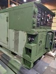
Some more pics.... pulled it out this morning to wash the spilled fuel off (from the tank well nuts and return fuel line replacement) and move some things around. Also for that hole where the output cables come out, there is a bolt on plate. You have two blank ones without a hole, one on the opposite side of the trailer and one in the middle panel where the big plastic wrench hangs.

Can see where I installed the big 32-04 (shell size 32) connector where the output cables exit was as well as the 20A (GFCI duplex where the NATO connector was), the 50A rv connector, and the smaller circular connector for the 20A GFCI corded (50 foot) duplex receptacle.

Shot of the knife switch to replace the ground bonding strap. This is far easier to use then bolting/unbolting the original metal bar.

Plus a couple more photos. Earlier shot where I started coating the paint with Penetrol - makes a huge difference and really brings the faded color back and a beauty shot with it behind my H2.

4.jpg5.jpg6.jpg7.jpg8.jpgpurty.jpg
 

Mullaney

Well-known member
Steel Soldiers Supporter
Supporting Vendor
7,716
19,766
113
Location
Charlotte NC
That part on the trailer frame, Zed got it. The TM shows a wing nut but mine is a hex, unbolt it and it sits on top of a jack for lifting the trailer to change a tire.

Some more pics.... pulled it out this morning to wash the spilled fuel off (from the tank well nuts and return fuel line replacement) and move some things around. Also for that hole where the output cables come out, there is a bolt on plate. You have two blank ones without a hole, one on the opposite side of the trailer and one in the middle panel where the big plastic wrench hangs.

Can see where I installed the big 32-04 (shell size 32) connector where the output cables exit was as well as the 20A (GFCI duplex where the NATO connector was), the 50A rv connector, and the smaller circular connector for the 20A GFCI corded (50 foot) duplex receptacle.

Shot of the knife switch to replace the ground bonding strap. This is far easier to use then bolting/unbolting the original metal bar.

Plus a couple more photos. Earlier shot where I started coating the paint with Penetrol - makes a huge difference and really brings the faded color back and a beauty shot with it behind my H2.

View attachment 839523View attachment 839524View attachment 839525View attachment 839526View attachment 839527View attachment 839528
.
If you have a burning desire to make that green paint look better - you could always paint it white to match your truck. One of the other guys on here has a camping setup in a small military trailer. He painted it to match his white truck too. Looked amazingly good that way...
 

Ray70

Well-known member
2,595
5,909
113
Location
West greenwich/RI
A bit late now if you already wiped it down with Penetrol, but the best thing I have found ( that lasts ) for renewing faded paint is to simply spray the machine with satin / matt / semi-gloss , whatever you want... Rattle can clear coat.
I don't suggest gloss because it looks too shiny and fake...
Especially if you machine was camo, just spray the entire thing and it will have a lasting low-luster sheen as well as extra protection from UV, water etc.
 

MixManSC

Member
35
77
18
Location
Columbia SC
I did consider spraying it with a matte clear..... Penetrol holds up surprisingly well (some of the "rat rods" that you see where they want to keep the vintage look use it as well) for a few years in my experience so I just went with that since I already had it around.

My welding guy came to drop a trailer off at my sign shop and tool a look. He thinks he can pretty easily get well over 100 gallons of fuel tank underneath it. He is going to pull the gen off, flip the trailer over, pull the axle, and build it from the bottom that way then re-install the axle a few inches higher up to drop the overall trailer height. Saw a thread on here where a couple of others have done that and looks to be a not too difficult modification to make. That with some Chevy 8x165 stock wheels with some smaller tires should get its tongue height down to a level to comfortably tow with any typical full size truck.

Got a 3" vented, locking diesel fuel cap, neck, pickup tube, sending unit flange, and a couple of other bungs from Boydwelding and also got a diesel transfer pump that will also be integrated for filling our tractor and whatnot from the trailer integrated fuel tank.

As it is, with my H2. That is lifted 2 inches plus I have 37's instead of the stock 325's (roughly 34.65") and I have the pintle hook plate upside down with the pintle as high as it will go to tow it level. A stock H2 would not even be able to tow it level. I plan on selling my H2 as living rural it is impractical so I'm planning on eventually getting a GMC or Chevy 2500 4x4 Duramax which will become the primary vehicle for towing it around (which probably will not realistically be often).
 

MixManSC

Member
35
77
18
Location
Columbia SC
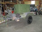
Smallish update.... Got a pair of GM HD truck wheels (plain steel ones). Scuffed and rattle canned them flat black. Rust Oleum flat black with built in primer is more of a satin back (their industrial enamel flat black is much flatter). Found a pair of used BFG Mud Terrain KM3 in 265/70/R16 (10 ply load range E) to put on the wheels. Bolted them on in place of the big 37's. Certainly changes the look. Dropped the height overall by right about 2.5 inches. Does not seem like much but very noticeably lower down. Still might have my welder friend raise the axle up by a couple more inches when he does the custom belly fuel tank to bring it down a bit more.

Seems like going from a 37" down to a 30.6" would have dropped it closer to 3". Regardless I'm happy. I'm in with the wheels, tires, mounting and balanced right about $300. Hoping I can sell the two military wheels locally for close to that much (they are in excellent shape).

IMG_3782.jpg
 

MixManSC

Member
35
77
18
Location
Columbia SC
And one more....

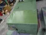
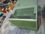
My solution for the side air intakes and bottom hole as I mentioned before was to install aluminum screen inside those. The top one I did not want to go that route as I felt that a finer mesh screen would be too restrictive (probably would be just fine though) but wanted to keep it open. So I debated a couple of solutions. What I ended up with is a flexible banner material. Since I have a sign shop I have this in stock. Most banners are fairly weak and not really designed for heavier winds and whatnot but we have a different one that is an 1000 denier 18oz banner material that is a heavy duty type specifically for pole banners. I've had banners up at Ft Jackson on this material that still are holding up after 5 years on the Chaplain School.

So I just printed some "close to" OD green on it (both sides) and cut a piece to fit (30-5/8" x 20"). On the leading edge above the fuel fill end I folded it over a 1/2" strip of thin aluminum and riveted that down. For the rest of the perimeter I used heavy duty 3M Dual Lock which is a type of super duty velcro. Locks it down tight when not in use and then just flip it open when you are going to be running the gen. Came out pretty good I think.

Couple of pics and one final shot of it with the new smaller wheels and tires on the trailer. It is now heading home and I'll be pulling the gen off and then having a friend built the custom belly fuel tank on the trailer.

vent1.jpg

vent2.jpg

h222.jpg
 
Last edited:

Guyfang

Moderator
Staff member
Moderator
16,766
24,080
113
Location
Burgkunstadt, Germany
And one more....

My solution for the side air intakes and bottom hole as I mentioned before was to install aluminum screen inside those. The top one I did not want to go that route as I felt that a finer mesh screen would be too restrictive (probably would be just fine though) but wanted to keep it open. So I debated a couple of solutions. What I ended up with is a flexible banner material. Since I have a sign shop I have this in stock. Most banners are fairly weak and not really designed for heavier winds and whatnot but we have a different one that is an 1000 denier 18oz banner material that is a heavy duty type specifically for pole banners. I've had banners up at Ft Jackson on this material that still are holding up after 5 years on the Chaplain School.

So I just printed some "close to" OD green on it (both sides) and cut a piece to fit (30-5/8" x 20"). On the leading edge above the fuel fill end I folded it over a 1/2" strip of thin aluminum and riveted that down. For the rest of the perimeter I used heavy duty 3M Dual Lock which is a type of super duty velcro. Locks it down tight when not in use and then just flip it open when you are going to be running the gen. Came out pretty good I think.

Couple of pics and one final shot of it with the new smaller wheels and tires on the trailer. It is now heading home and I'll be pulling the gen off and then having a friend built the custom belly fuel tank on the trailer.

View attachment 842054

View attachment 842055

I saw this done on some gen sets, someplace here in Germany, just before I stopped contracting. Can not remember where or who. Good idea!
 

MixManSC

Member
35
77
18
Location
Columbia SC
No pics but an update to keep this fresh for now.... The trailer is coming along. Went one step further than what I've seen in a couple of other threads where members have modified their LTT trailers to raise the axle up higher (in order to lower the trailer). As mentioned I did change it up to the vastly lighter wheels with the smaller tires. That dropped it some but not enough. So basically we have cut the main axle mounting plate (large thick piece of C channel) near flush to the frame and have remounted the axle flush. It is still standing on end right now but we calculated (also eliminating the 2 shocks) that the torsion axle can handle it no problem even with the load plus the additional fuel load and will still have about 12" of ground clearance with plenty of travel that there will be no issues with the tires hitting the fenders or anything.

I will try to get some pictures in the next week. The custom belly fuel tank will be approximately 68x48x12 which comes out to nearly 160 gallons (after notching for the front tow bar, adding a few baffle panels to prevent sloshing while towing) I'm figuring a usable capacity of just over 150 gallons. Going to situate the gen a bit further forward on the trailer with the control panel at the rear for ease of access. In the gap at the rear between the frame and where the gen site is where we are installing the fuel fill cap and fuel level gauge. Hard to describe well though so I really need to take some photos.
 

Abrant23

Active member
Steel Soldiers Supporter
145
186
43
Location
Charleston, SC
I will try to get some pictures in the next week. The custom belly fuel tank will be approximately 68x48x12 which comes out to nearly 160 gallons (after notching for the front tow bar, adding a few baffle panels to prevent sloshing while towing) I'm figuring a usable capacity of just over 150 gallons. Going to situate the gen a bit further forward on the trailer with the control panel at the rear for ease of access. In the gap at the rear between the frame and where the gen site is where we are installing the fuel fill cap and fuel level gauge. Hard to describe well though so I really need to take some photos.

Don't forget that anything over 119 gallons in a single container will require hazmat placards and an endorsement on your drivers license to pull it on the highway. Might be worth putting in a solid baffle and two fill necks to in essence make it "two separate containers" with each being under the 119 gallon mark.


Alvin
 

MixManSC

Member
35
77
18
Location
Columbia SC
Great info. I'll be talking with my welder who is building this out later today. Going to tell him we either need to reduce it below 119 or divider it into two separate tanks with separate fill necks.
 
Top