• Steel Soldiers now has a few new forums, read more about it at: New Munitions Forums!

  • Microsoft MSN, Live, Hotmail, Outlook email users may not be receiving emails. We are working to resolve this issue. Please add support@steelsoldiers.com to your trusted contacts.

has my MEP-831 governor magnet been adjusted?

gstirling

Member
Steel Soldiers Supporter
143
17
18
Location
knoxville tn
my generator (MEP-831) ran poorly when i got it, after following the TM with no improvement i got the new governor from Kloppk (highly recommended) and when adjusted per the TM it would still not run quite right but much better (surging). a bit of tweeking and i found by setting the gap a bit to large (per the TM) the machine runs perfectly, starts great, takes load, rejects load, etc.. with one exception - it will not shut off on its own (when the off switch or E-stop is pushed) you have to hold the actuator arm against the magnet. When shutdown using just the off switch or E-stop the arm will pull to the magnet, start to shutdown, then let go, and the engine will continue to run (badly) smoking etc..

i then noticed some caulk on the pipe holding the magnet to the governor actuator arm and no wire lock on the magnet set screw as others indicated there should be (there is a wire lock on the engine throttle lever). so was thinking maybe some one in the past did (the forbidden per the TM) adjust the magnet. attached are some pictures. Could you guys compare mine to your machine's and see what you think? or am i just not adjusting my machine correctly.

I am not willing to touch the magnet till i can be fairly certain it has been tampered with and i'm just not dialing in my machine correctly, then if no other ideas from anyone, will try adjusting it.

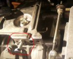
first pic (left most) just shows how far "in" the magnet is in side its holder.
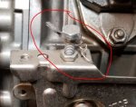
second shows the screw that holds the magnet in place (no lock wire or hole for one???
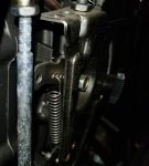
third shows the caulk/glue around the base of the magnet holder, normal???
fourth shows how i have it adjusted - this is as close as the magnet can pull the target (not correct per TM, but at this setting the gen runs great!) FYI - engine is off in pic i'm just pushing the target to the magnet
thanks for any input.


20180228_174401.jpg20180228_174419.jpg20180228_174440.jpg20180228_174505.jpg
 

kloppk

Well-known member
Steel Soldiers Supporter
2,145
3,526
113
Location
Pepperell, Massachusetts
There certainly shouldn't be a gap between the target and the magnet as shown in pic 4 when the set is off and the target is pushed by hand toward the magnet. It should travel all the way to the magnet and stick.

No calk (epoxy?) on my magnets.
20180227_105700.jpg

I noticed the locking wire is missing from the adjusting bolt shown in picture #3.
Possibly someone in the past removed the factory locking wire and attempted to adjust it?
The bolt looks shiny as if it were replaced with a S.S. bolt. Can you spot a hole thru the head of the bolt where the locking wire should be?
If not then the factory adjustment bolt was replaced...
This bolt..
Adj Bolt.JPG

What the adjustment bolt should look like with the locking wire and lead seal from the factory.
Adj Bolt 2.JPG
 
Last edited:

gstirling

Member
Steel Soldiers Supporter
143
17
18
Location
knoxville tn
thanks - will check that out to night. hadn't looked at the bolt you pointed out and that looks like it controls engine stop side of the governor system... I had focused on the magnet/actuator side.
 

DieselAddict

Well-known member
Steel Soldiers Supporter
2,532
2,059
113
Location
Efland, NC
That altered bolt sets the maximum mechanical governor limit. That is an important adjustment. If you aren't seeing the engine overspeed I would leave it alone for now. We can circle back and get everything tweaked in once you have some of the other issues resolved.

There is a procedure for testing the magnet adjustment. Take a look at this post and the few after it - https://www.steelsoldiers.com/showt...ubleshooting&p=1664424&viewfull=1#post1664424

That will get you pointed in the right direction on testing the magnet/target pull-off adjustment.
 

gstirling

Member
Steel Soldiers Supporter
143
17
18
Location
knoxville tn
Chris

thanks for the links, reading all bazillion of them. will check magnet pull off etc.. on an unrelated note: one of the things talked about in those posts that happens to me also is a weak over current circuit breaker on the convenience outlet GFI unit, like in the posts found i ran down the replacement part - and found the exact part is pretty expensive. any reason you can't substitute a 10-15 or 20amp ckt bkr in a fab'ed up box and a home depot type GFI outlet? My GFI trips on almost every start, but once reset is stable, i read in the posts you recommended reviewing that grounding the unit may help solve this - did i read that right? my unit did not come with the grounding rods so i had not been using one. should I? so far all loads have just been plug in tools and heaters. so hand't thought it necessary.
 

DieselAddict

Well-known member
Steel Soldiers Supporter
2,532
2,059
113
Location
Efland, NC
I'll have to check but if I remember correctly the internal wiring for the convenience outlet was pretty light. I don't think it would be suitable for a 20a circuit. I can check when I'm back home on Saturday though.

If you wan to use higher current devices I do recommend using the output lugs and making up GFI/breaker/outlets that will work better for what you need.
 

Dewie38

Active member
152
189
43
Location
Milford Ct
The gap means that the armature inside the actuator is bottoming out.
Lift the actuator arm to full fuel, lock the locking pin in and hit the top of the actuator arm with your closed fist (pinky side of hand, hitting the arm downward.)
Lift the arm off the locking pin and see if the actuator now closes all the way.
If it does then the set screws holding the arm that goes into the actuator that go to the armature are loose or weren't set right from the factory.
 

kloppk

Well-known member
Steel Soldiers Supporter
2,145
3,526
113
Location
Pepperell, Massachusetts
I just spent some time looking at the mechanical governor operation and the two stop screws.
The upper vertical locking bolt sets the governor spring tension and limits the travel of the black STOP RUN knob toward the RUN position.
The lower horizontal locking bolt and with spring pin sets the maximum throttle.

gsterling - Check which hole the upper end of the larger governor spring is hooked into. Both of mine set look like this.
Governor Spring.jpg
 

gstirling

Member
Steel Soldiers Supporter
143
17
18
Location
knoxville tn
yes it is (convenience outlet wiring being light gauge, looks to be 14 at best), your idea is a better(safer) way to go and cheaper than changing out the old GFI with a new "correct' GFI with 15 amp unit. By the way i'm using the unit to power tools for a shed i'm building for my M936, so the circular saw, if run for short cuts is fine on the 10 amp outlet, but on long hard continuous cuts (ripping a green 2x length wise) the over current on the convenience outlet will open before i can cut down all 12 ft (the slow blow thermal). the saw really needs a full 15 or 20 amp outlet. will make a hard wire 15 amp GFI outlet this week as you suggested.
 
Last edited:

gstirling

Member
Steel Soldiers Supporter
143
17
18
Location
knoxville tn
thanks, i will check, but my memory is my spring is in the first or second hole towards the fuel filter side, will try moving it to where yours is, that would increase spring tension.

thanks all for the feed back.
 
Top
AdBlock Detected

We get it, advertisements are annoying!

Sure, ad-blocking software does a great job at blocking ads, but it also blocks useful features of our website like our supporting vendors. Their ads help keep Steel Soldiers going. Please consider disabling your ad blockers for the site. Thanks!

I've Disabled AdBlock
No Thanks