• Steel Soldiers now has a few new forums, read more about it at: New Munitions Forums!

  • Microsoft MSN, Live, Hotmail, Outlook email users may not be receiving emails. We are working to resolve this issue. Please add support@steelsoldiers.com to your trusted contacts.

Help with smoking glow plug switch

kabar1

New member
248
-1
0
Location
Cleveland Tennessee
photo (9).JPGphoto (5).JPGphoto (6).JPGphoto (7).JPG
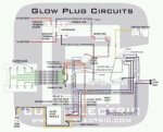
I know its not factory , i didn't put it on. The switch worked good for a month then started burning up, its wired with two 10 gauge red wires one looks to be coming off the coil pack and the other the power bar. Any ideas? i replaced the switch with a 20 amp switch and with in a few minutes it started smoking too, Also the belts are squelling now and im not getting a full charge any more.:confused::confused:
 
Last edited:

doghead

4 Star General /Moderator
Staff member
Super Moderator
Steel Soldiers Supporter
26,247
1,174
113
Location
NY
I can't determine much from your pictures.

If you using a manual push button, it needs to activate a relay. You do not want to switch that much amperage with a pushbutton.


In stock configuration, all you need to do to manually operate the GP relay is, momentarily ground the light blue wire(push button and 14ga wire).
 

doghead

4 Star General /Moderator
Staff member
Super Moderator
Steel Soldiers Supporter
26,247
1,174
113
Location
NY
In order to work with stock wiring, the GP relay needs to be isolated from ground(no continuity between any of the 4 terminals, to it's mount(chassis).
 

kabar1

New member
248
-1
0
Location
Cleveland Tennessee
I was hoping you would see the post! Which blue wire? One from in engine compartment? What do i need to do with the to wire going to the push button glow plug switch? Thanks for your help as always doghead!!
 

doghead

4 Star General /Moderator
Staff member
Super Moderator
Steel Soldiers Supporter
26,247
1,174
113
Location
NY
One of the 2 small terminals on the relay has a light blue wire. That one just needs to be "touched to ground" to make a stock system function "manually".

Obviously your system is not "stock".

You'll need to either reconfigure it correctly, or make your own system(if you want to).

You'll need to test all components too.

First, I would confirm the GP relay is an isolated ground relay. That may determine which way we go. Then, it depends if your relay is good.

Ultimately, what do you want/need?

Is time of the essence?
 
Last edited:

kabar1

New member
248
-1
0
Location
Cleveland Tennessee
I would like to reconfigure it correctly , I would not like to have it down for a while , how do I test and make sure it's grounded correctly I guess where do I begin ?
 

doghead

4 Star General /Moderator
Staff member
Super Moderator
Steel Soldiers Supporter
26,247
1,174
113
Location
NY
Do you have a digital multi meter, and know how to use it?
 

doghead

4 Star General /Moderator
Staff member
Super Moderator
Steel Soldiers Supporter
26,247
1,174
113
Location
NY
Also, do you have the Tms downloaded on your computer?

The schematics are in the back of the -20 and -34 TMs

Also, there is a step by step troubleshooting section for the GPs in the -20TM
 

doghead

4 Star General /Moderator
Staff member
Super Moderator
Steel Soldiers Supporter
26,247
1,174
113
Location
NY
posted earlier today
As far as the TMs, here's a quick lesson on them.

TM 9-2320-289-10 is the owners manual. Gotta have it and I keep a hard copy in my trucks.
TM 9-2320-289-20 is Unit Maintenance. Consider this for light repairs and maintenance.
TM 9-2320-289-20P is the parts manual to support the above manual.
TM 9-2320-289-34 is the depot manual which covers major repairs and overhaul
TM 9-2320-289-34P is the parts manual to support the depot manual.

Forget trying to open and use them on the site, waste of time. Right click on them and save them to your computer for faster and easier searching.
 

85CUCVtom

Active member
712
25
28
Location
Lakewood, Ohio
Thank you! You wouldn't care to suggest a few page numbers? I found one schematic in 34 Tm but no detail on wich wires are wich
The wires are identified in the diagrams. There should be small text under the "wire" in the diagram. I posted a page that should help you out and a colored diagram from CUCV Electric. They are a little easier to read. I suggest you print the diagrams out, laminate them and keep them in a binder in the garage.

I had a hard time at first with the TM's, not with the schematics but with actually finding what I needed. Gotta learn to use them, they are a huge resource when working on our trucks.
 

Attachments

Warthog

Moderator
Super Moderator
Steel Soldiers Supporter
13,774
231
63
Location
OKC, OK
You also need to read the first few pages of the troubleshooting section. It explains how to read the details of the wiring diagrams.

Your GP wiring is really jacked up. Read and watch the sticky that talks about the GP system.
 
Last edited:

kabar1

New member
248
-1
0
Location
Cleveland Tennessee
Yes this is going to be painful, i replaced and rewired the relay per the schematic removed the wires for switch. The picture with the light blue has a plug on the end of it and goes no were and cant find it on schematic, it comes out of the same bundle that comes out of glow plug module, I also have no juice i unhooked the back battery positive to keep the switch from smoking would that of drained both batteries down , any one know were the stray wire goes it looks like a factory plug on the end. It looks like a orange wire is hooked to it in the picture but nothing is its the wire im holding
 
Last edited:

Warthog

Moderator
Super Moderator
Steel Soldiers Supporter
13,774
231
63
Location
OKC, OK
That blue wire is for the M1010 aux fuel pump. Not used on your truck.

The light blue wire DH was talking about is already connected to the relay. It is very faded blue and the other small wire is pinkish.

Do you have a battery charger? Have you taken the time to learn how to use your multimeter? Youtube has many videos to teach you the basics.

You will need to charge the batteries and then start checking for voltage at different spots.
 
Last edited:

doghead

4 Star General /Moderator
Staff member
Super Moderator
Steel Soldiers Supporter
26,247
1,174
113
Location
NY
I'm confused why the relay is different in the first and last pics.
 
Top
AdBlock Detected

We get it, advertisements are annoying!

Sure, ad-blocking software does a great job at blocking ads, but it also blocks useful features of our website like our supporting vendors. Their ads help keep Steel Soldiers going. Please consider disabling your ad blockers for the site. Thanks!

I've Disabled AdBlock
No Thanks