• Steel Soldiers now has a few new forums, read more about it at: New Munitions Forums!

  • Microsoft MSN, Live, Hotmail, Outlook email users may not be receiving emails. We are working to resolve this issue. Please add support@steelsoldiers.com to your trusted contacts.

Help with wiring

Toddbo35

Member
41
62
18
Location
Hitchcock, Texas
Easy fix. The purple with white trace is 12 volt from ignition switch. Solid purple is solenoid output 24 volt to starter. Red is 24 volt supply. This red wire is protected by a fusible link at the 24 volt bus, right side of firewall engine compartment. You need a wire to ground from the other coil terminal.

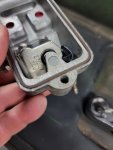
Well I got the doghead relay installed today. Motor spins over now. However I pulled the cover off the injection pump and just as you had mention the back screw was most definitely broken off. Spent a couple hours trying to get it out . Looks like I'm gonna have to drill it out.

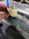
As far as the solenoids on the IP cover, they're both 24 volt. Not sure why I only have 12 volts supply to them. Another question I have is the glow plugs.......how much voltage should they have going to them when the relay is on?
 

Attachments

ezgn

Well-known member
650
1,039
93
Location
Lake Elsinore Ca.
Well I got the doghead relay installed today. Motor spins over now. However I pulled the cover off the injection pump and just as you had mention the back screw was most definitely broken off. Spent a couple hours trying to get it out . Looks like I'm gonna have to drill it out.

As far as the solenoids on the IP cover, they're both 24 volt. Not sure why I only have 12 volts supply to them. Another question I have is the glow plugs.......how much voltage should they have going to them when the relay is on?
The glow plugs are always 12 volts at the glow plugs themselves. With or without the dog head conversion. The dog head conversion just by passes the resistor coils on the firewall witch drop the volts down from 24 volt to 12 volts. Good work, doing good.
Well I got the doghead relay installed today. Motor spins over now. However I pulled the cover off the injection pump and just as you had mention the back screw was most definitely broken off. Spent a couple hours trying to get it out . Looks like I'm gonna have to drill it out.

As far as the solenoids on the IP cover, they're both 24 volt. Not sure why I only have 12 volts supply to them. Another question I have is the glow plugs.......how much voltage should they have going to them when the relay is on?
 

ezgn

Well-known member
650
1,039
93
Location
Lake Elsinore Ca.
Well I got the doghead relay installed today. Motor spins over now. However I pulled the cover off the injection pump and just as you had mention the back screw was most definitely broken off. Spent a couple hours trying to get it out . Looks like I'm gonna have to drill it out.

As far as the solenoids on the IP cover, they're both 24 volt. Not sure why I only have 12 volts supply to them. Another question I have is the glow plugs.......how much voltage should they have going to them when the relay is on?
According to Keith J you have a foreign IP that does not work on any CUCV. Once you get the right Injection pump on there you should be able to start that baby up! The only thing on a CUCV that is 24 volt is the starter.
 

Keith_J

Well-known member
3,657
1,323
113
Location
Schertz TX
The glow plugs are always 12 volts at the glow plugs themselves. With or without the dog head conversion. The dog head conversion just by passes the resistor coils on the firewall witch drop the volts down from 24 volt to 12 volts. Good work, doing good.
Doghead modification is for starter only.

The glow plug system uses a pair of ballast resistors on the center firewall to divide voltage to 12 volts for the 12 volt glow plugs.
 

Keith_J

Well-known member
3,657
1,323
113
Location
Schertz TX
Well I got the doghead relay installed today. Motor spins over now. However I pulled the cover off the injection pump and just as you had mention the back screw was most definitely broken off. Spent a couple hours trying to get it out . Looks like I'm gonna have to drill it out.

As far as the solenoids on the IP cover, they're both 24 volt. Not sure why I only have 12 volts supply to them. Another question I have is the glow plugs.......how much voltage should they have going to them when the relay is on?
Ouch. Not an easy screw to remove due to size. I've done it once. Be sure to cover the pump with multiple layers of tape to keep the innards clean.

Before covering the pump, check the governor and metering valve as mentioned, look over the video I posted for locating the metering valve.

If you can't get Diesel Mechanic in a Bottle, Berryman B12 spray also dissolves the varnish and evaporates fast. When the metering valve frees up, coat the inside with a good penetrating oil or clean diesel.

Once you get the broken screw out and can seal the pump, I can instruct how to wire in a relay to make the 24 volt solenoids to be signaled by the 12 volt system. Basically this would tale 24 volts from the top bus bar on passenger side firewall, then use the pink wire to switch the 24 volts on with key in engine on.

Or you could buy a core pump from Hillbilly Wizard for $125 and use the cover only.


You need a normally open , 4 pin relay. Pin 85 goes to ground, 86 goes to the pink wire. Get 24 volt fused from the firewall bus top to pin 30. Connect pin 87 to the energized to run solenoid in the pump.

Same thing for the green wire.
 
Last edited:

Toddbo35

Member
41
62
18
Location
Hitchcock, Texas
Ouch. Not an easy screw to remove due to size. I've done it once. Be sure to cover the pump with multiple layers of tape to keep the innards clean.

Before covering the pump, check the governor and metering valve as mentioned, look over the video I posted for locating the metering valve.

If you can't get Diesel Mechanic in a Bottle, Berryman B12 spray also dissolves the varnish and evaporates fast. When the metering valve frees up, coat the inside with a good penetrating oil or clean diesel.

Once you get the broken screw out and can seal the pump, I can instruct how to wire in a relay to make the 24 volt solenoids to be signaled by the 12 volt system. Basically this would tale 24 volts from the top bus bar on passenger side firewall, then use the pink wire to switch the 24 volts on with key in engine on.

Or you could buy a core pump from Hillbilly Wizard for $125 and use the cover only.


You need a normally open , 4 pin relay. Pin 85 goes to ground, 86 goes to the pink wire. Get 24 volt fused from the firewall bus top to pin 30. Connect pin 87 to the energized to run solenoid in the pump.

Same thing for the green wire.
I'm gonna check with a friend of mine for a new IP cover first . If that fails I will order from hillbilly wizard. I really don't want to modify the electrical. Thank you again for the help
 

Keith_J

Well-known member
3,657
1,323
113
Location
Schertz TX
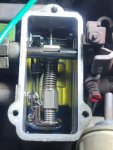
Good deal. Easy to test the IP cover solenoids when off the pump. You can get the sealing kit from Badger Diesel, they sell through Amazon too.

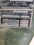
If the current pump body is indeed a 2829-4520, it won't have the flex ring issue of the 1984-1985 pumps. There is a MWO data plate under the Chevrolet Data plate, these are Maintenance Work Orders. I cannot read this plate from your photos, looks to be only one MWO which could have been the IP swap to the 4520 pump.
 
Last edited:

Keith_J

Well-known member
3,657
1,323
113
Location
Schertz TX
Very good news. The original pump was a DB2829-4267, this was superseded by DB2829-4520. From the broken screw on the cover, it appears someone tried a field fix.
Make sure to keep it clean, see if the metering valve operates freely before buttoning it back together. The cover gasket should be good to reuse, the throttle shaft seals are the most likely to leak.
I really like Diesel Mechanic in a Bottle for injection pump cleaning. And 30 seconds in an ultrasonic cleaner is the only way to get cleaner parts.
 

Toddbo35

Member
41
62
18
Location
Hitchcock, Texas
Very good news. The original pump was a DB2829-4267, this was superseded by DB2829-4520. From the broken screw on the cover, it appears someone tried a field fix.
Make sure to keep it clean, see if the metering valve operates freely before buttoning it back together. The cover gasket should be good to reuse, the throttle shaft seals are the most likely to leak.
I really like Diesel Mechanic in a Bottle for injection pump cleaning. And 30 seconds in an ultrasonic cleaner is the only way to get cleaner parts.
What's the difference between DB2829-4520 and DB2829-4521. I found a few 4521 used pumps. Just wanna make sure it's the same as what I have.
 

Keith_J

Well-known member
3,657
1,323
113
Location
Schertz TX
What's the difference between DB2829-4520 and DB2829-4521. I found a few 4521 used pumps. Just wanna make sure it's the same as what I have.
The 4521 is a 4520 with low viscosity fuel upgrades. The transfer pump blades and liner are replaced in order to use JP8 that has viscosity of 1.2 Centi Stokes, abbreviated 1.2 cStk in literature. Calibration is identical.
 

Toddbo35

Member
41
62
18
Location
Hitchcock, Texas
The 4521 is a 4520 with low viscosity fuel upgrades. The transfer pump blades and liner are replaced in order to use JP8 that has viscosity of 1.2 Centi Stokes, abbreviated 1.2 cStk in literature. Calibration is identical.
Wow dude......you are impressive. Your wealth of knowledge is very impressive. Idk what you do for a living but you probably should be paid alot more. Thank you once again
 

Keith_J

Well-known member
3,657
1,323
113
Location
Schertz TX
I've been reading up on these vehicles and injection pumps as I can't do much other work. And TV stinks, not to mention the current state of affairs.

The CUCV manuals are public domain. I've found the pump specs on line too..part of my turbo upgrade. Found a DB2829 calibration for 250 Hp 😉.
 

Toddbo35

Member
41
62
18
Location
Hitchcock, Texas
Well I messed with her a little bit today. I noticed that I have 24 volts going to the glow plugs. I traced back and it appears that the resistors have 24 volts on both sides. What are the chances that the glow plugs are bad now due to the 24 volts going to them?
 

Keith_J

Well-known member
3,657
1,323
113
Location
Schertz TX
Well I messed with her a little bit today. I noticed that I have 24 volts going to the glow plugs. I traced back and it appears that the resistors have 24 volts on both sides. What are the chances that the glow plugs are bad now due to the 24 volts going to them?
Completely normal, resistors only drop voltage inversely proportional to current. If you are getting 24 volts to the glow plugs, it means no current and the glow plugs are failed open.

The firewall resistors have the same resistance as the combined resistance of all 8 glow plugs, this divides the voltage in half. When a glow plug fails, the remaining glow plugs see higher voltage and more current which would lead to cascade failure if the controller is not correctly connected with the thin orange wire on the GP solenoid output (same terminal as the 2 thicker orange wires). This orange wire senses higher voltage and reduces glow time, preventing burnout.
At current Texas temperature, my CUCV requires 6 seconds of pre glow and starts immediately. Just tested it today. Your temperature sensor may differ but should be under 15 seconds.
 

ezgn

Well-known member
650
1,039
93
Location
Lake Elsinore Ca.
Well I messed with her a little bit today. I noticed that I have 24 volts going to the glow plugs. I traced back and it appears that the resistors have 24 volts on both sides. What are the chances that the glow plugs are bad now due to the 24 volts going to them?
[/
 

ezgn

Well-known member
650
1,039
93
Location
Lake Elsinore Ca.
Completely normal, resistors only drop voltage inversely proportional to current. If you are getting 24 volts to the glow plugs, it means no current and the glow plugs are failed open.

The firewall resistors have the same resistance as the combined resistance of all 8 glow plugs, this divides the voltage in half. When a glow plug fails, the remaining glow plugs see higher voltage and more current which would lead to cascade failure if the controller is not correctly connected with the thin orange wire on the GP solenoid output (same terminal as the 2 thicker orange wires). This orange wire senses higher voltage and reduces glow time, preventing burnout.
At current Texas temperature, my CUCV requires 6 seconds of pre glow and starts immediately. Just tested it today. Your temperature sensor may differ but should be under 15 seconds.
Thanks Keith, I think your explanation is the first time that I now fully understand the way the system works. I did the glow plug resistor bypass on my truck 20 years ago and never looked back.
 
Top
AdBlock Detected

We get it, advertisements are annoying!

Sure, ad-blocking software does a great job at blocking ads, but it also blocks useful features of our website like our supporting vendors. Their ads help keep Steel Soldiers going. Please consider disabling your ad blockers for the site. Thanks!

I've Disabled AdBlock
No Thanks