• Steel Soldiers now has a few new forums, read more about it at: New Munitions Forums!

  • Microsoft MSN, Live, Hotmail, Outlook email users may not be receiving emails. We are working to resolve this issue. Please add support@steelsoldiers.com to your trusted contacts.

Help with wiring

Keith_J

Well-known member
3,657
1,323
113
Location
Schertz TX
Is it easier just to bypass them and run 12 volts to the relay?
If the glow plug controller fails in a certain way or the glow plug solenoid sticks closed, the glow plugs can cascade fail as voltage to plugs increases when one or more plugs fail.

I had the solenoid fail three years ago, when I replaced it, all three orange wires were connected to the output terminal. Last year, I had difficulty starting AND far shorter glow times..three failed glow plugs. Not a real cascade failure as it took three days to get time to do the full swap. All eight came out easily. With new Bosch Duratherms, normal pre glow time returned with instant starting.

The TMs have an error showing the thin orange wire going to the input terminal on the glow plug solenoid. Per design intent, this wire is voltage sense to prevent cascade failure which shuts off voltage to the glow plugs when over a certain level.

Edit to add the certain voltage is 16.2 volts. I have a 42 page tech paper on the specifications and operation of this system.

I would keep the 24 volt system stock, correcting the GP solenoid voltage sense line. When it is incorrectly connected to the solenoid input, voltage varies from 24 with GPS off to 12-16 when GPA are on. This may be the cause of failed GP controller cards, cascade failure of plugs and other faults.
 
Last edited:

Toddbo35

Member
41
62
18
Location
Hitchcock, Texas
If the glow plug controller fails in a certain way or the glow plug solenoid sticks closed, the glow plugs can cascade fail as voltage to plugs increases when one or more plugs fail.

I had the solenoid fail three years ago, when I replaced it, all three orange wires were connected to the output terminal. Last year, I had difficulty starting AND far shorter glow times..three failed glow plugs. Not a real cascade failure as it took three days to get time to do the full swap. All eight came out easily. With new Bosch Duratherms, normal pre glow time returned with instant starting.

The TMs have an error showing the thin orange wire going to the input terminal on the glow plug solenoid. Per design intent, this wire is voltage sense to prevent cascade failure which shuts off voltage to the glow plugs when over a certain level.

Edit to add the certain voltage is 16.2 volts. I have a 42 page tech paper on the specifications and operation of this system.

I would keep the 24 volt system stock, correcting the GP solenoid voltage sense line. When it is incorrectly connected to the solenoid input, voltage varies from 24 with GPS off to 12-16 when GPA are on. This may be the cause of failed GP controller cards, cascade failure of plugs and other faults.

Well only 2 of the 8 glow plugs are willing to surrender. Looks like I need a removal tool. Any advice on which one is best?
 

Keith_J

Well-known member
3,657
1,323
113
Location
Schertz TX
Well only 2 of the 8 glow plugs are willing to surrender. Looks like I need a removal tool. Any advice on which one is best?
Leroy Diesel. Don't have a link right now but it is online.


I have heard of running the engine to force the plugs out. But 1800 PSI on the 5.2 mm bore means a good deal of kinetic energy so wrap it in heavy shop towel.

The other way is to raise the piston to TDC. Then remove the injector, break off the swollen tip and extract with curved hemostat pliers etc. The piston at TDC keeps the broken tip from entering the cylinder.

You didn't mention which cylinders have swollen tip plugs..low odds are best. #7 requires oil line removal. Even cylinders need back battery pulled.

Just got done with compression testing so memory is fresh.
 
Last edited:

Toddbo35

Member
41
62
18
Location
Hitchcock, Texas
Leroy Diesel. Don't have a link right now but it is online.


I have heard of running the engine to force the plugs out. But 1800 PSI on the 5.2 mm bore means a good deal of kinetic energy so wrap it in heavy shop towel.

The other way is to raise the piston to TDC. Then remove the injector, break off the swollen tip and extract with curved hemostat pliers etc. The piston at TDC keeps the broken tip from entering the cylinder.

You didn't mention which cylinders have swollen tip plugs..low odds are best. #7 requires oil line removal. Even cylinders need back battery pulled.

Just got done with compression testing so memory is fresh.
#2 and #6 were the only ones that volunteered. I bought the extraction tool from Leroys. Didn't know it but he is just up the highway from me. Not looking forward to the removal. Hillbilly wizard has shipped me the IP. Hopefully there's an end in sight after this.
 

Keith_J

Well-known member
3,657
1,323
113
Location
Schertz TX
With 6 swollen glow plugs, a better picture of the state of the engine appears. While the engine can start without functioning glow plugs, it takes a very long cranking time.

The Leroy tool can snap the tip off, usually the bit sticks in the head. It is best to bring each cylinder to top dead center when working on it so in the case of broken tip, the job doesn't turn into a head gasket replacement.
 

ezgn

Well-known member
650
1,039
93
Location
Lake Elsinore Ca.
With 6 swollen glow plugs, a better picture of the state of the engine appears. While the engine can start without functioning glow plugs, it takes a very long cranking time.

The Leroy tool can snap the tip off, usually the bit sticks in the head. It is best to bring each cylinder to top dead center when working on it so in the case of broken tip, the job doesn't turn into a head gasket replacement.
Okay Keith, my question to you, which maybe most others might already know is, how do you fine top dead center? Do you pull the valve covers off and go by the rockers relative to the amount of play? Thanks in advance.
 

Keith_J

Well-known member
3,657
1,323
113
Location
Schertz TX
Okay Keith, my question to you, which maybe most others might already know is, how do you fine top dead center? Do you pull the valve covers off and go by the rockers relative to the amount of play? Thanks in advance.
On the left side of the harmonic damper is a scale, with all glow plugs loose, you can roll the engine over with a socket on the damper bolt. Now you need to lay out quadrants on the damper...90° intervals. #1 TDC is marked with a slot across the damper outer ring. One chalk line at 180°, then two 90° either side. Measure and divide with a pi tape, if you have it, or with a tailor tape.

It matters not if the piston is on compression or exhaust, the tip cannot fall into the main chamber long as the piston is at TDC. Use firing order 1-8-7-2-6-5-4-3. Cylinder numbers are 1-7 odd front to rear left or driver's side. 2-8 even front to rear passenger or right side.
 
Last edited:

Toddbo35

Member
41
62
18
Location
Hitchcock, Texas
With 6 swollen glow plugs, a better picture of the state of the engine appears. While the engine can start without functioning glow plugs, it takes a very long cranking time.

The Leroy tool can snap the tip off, usually the bit sticks in the head. It is best to bring each cylinder to top dead center when working on it so in the case of broken tip, the job doesn't turn into a head gasket replacement.
Pull the injector on each cylinder to determine top dead center?
 

ezgn

Well-known member
650
1,039
93
Location
Lake Elsinore Ca.
On the left side of the harmonic damper is a scale, with all glow plugs loose, you can roll the engine over with a socket on the damper bolt. Now you need to lay out quadrants on the damper...90° intervals. #1 TDC is marked with a slot across the damper outer ring. One chalk line at 180°, then two 90° either side. Measure and divide with a pi tape, if you have it, or with a tailor tape.

It matters not if the piston is on compression or exhaust, the tip cannot fall into the main chamber long as the piston is at TDC. Use firing order 1-8-7-2-6-5-4-3. Cylinder numbers are 1-7 odd front to rear left or driver's side. 2-8 even front to rear passenger or right side.
Thank you for explaining the procedure. So you divide the damper into eight equal sections as you explained, and then follow the firing order by turning the damper from piston one to piston 8 as you remove the glow plugs and continue the procedure following the firing order. Hope I never have to use it, but it is good to learn. I hope I said that right.
 

Keith_J

Well-known member
3,657
1,323
113
Location
Schertz TX
Thank you for explaining the procedure. So you divide the damper into eight equal sections as you explained, and then follow the firing order by turning the damper from piston one to piston 8 as you remove the glow plugs and continue the procedure following the firing order. Hope I never have to use it, but it is good to learn. I hope I said that right.
It is a 90° V8 with cross plane crank. Meaning 1 and 2 have a common crank pin. So these pairs are 90° off. Ditto with 3 and 4, 5 and 6, 7 and 8. Divide the damper ring into 4 quadrants and use the lines to line up with the timing pointer, based on the firing order.
 

ezgn

Well-known member
650
1,039
93
Location
Lake Elsinore Ca.
It is a 90° V8 with cross plane crank. Meaning 1 and 2 have a common crank pin. So these pairs are 90° off. Ditto with 3 and 4, 5 and 6, 7 and 8. Divide the damper ring into 4 quadrants and use the lines to line up with the timing pointer, based on the firing order.
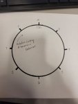
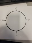
Got it!! I drew it out on a piece of paper. All 90's based on the firing order.
 

Keith_J

Well-known member
3,657
1,323
113
Location
Schertz TX
You got it now. One cylinder fires every 90° of crank rotation. For swollen GP removal, piston should be TDC for compression or exhaust, it doesn't matter. There is only 20 to 30 thousandths of an inch between the piston top and cylinder head which is 1/10th the diameter of an unswollen GP so any broken tip can be extracted from the injector port.
 
Last edited:

Toddbo35

Member
41
62
18
Location
Hitchcock, Texas
You got it now. One cylinder fires every 90° of crank rotation. For swollen GP removal, piston should be TDC for compression or exhaust, it doesn't matter. There is only 20 to 30 thousandths of an inch between the piston top and cylinder head which is 1/10th the diameter of an unswollen GP so any broken tip can be extracted from the injector port.
10-4 Tomorrow I will start the process and hopefully I will get the glow plugs replaced. Are the Ac delco G60 plugs ok? Is there another brand or model that's less likely to swell?
 

Keith_J

Well-known member
3,657
1,323
113
Location
Schertz TX
I had 13G in mine, factory as far can be determined. Vehicle had 9000 miles in 2012 when I liberated it from Ft McCoy WI. Had starting issues last year, 3 were burned out and 2 lost the spades on replacing, none were swollen. The starting difficulty also presented with much shorter pre glow, indicating the voltage sense circuit was properly working. This cuts the solenoid when voltage is over 16.2 at the solenoid output terminal. This is the thin orange wire, it must be connected to the same terminal as the two large orange wires.

I replaced with Bosch Duratherms which I modified with a file from 1/4" to 3/16". None have swollen when pulled to do compression testing and leak down analysis on the weak cylinder, #5 leaks at around 300 PSI into the cooling jacket. Yes, I have air at that pressure from my air rifle hobby. Actually put the compressor on the intake manifold as the 4500 PSI hose is only 20" long. I pulled the Schraeder valve from the GP adapter which has a 8mm Foster male QD, compatible with the industry standard QD for pre charged pneumatic air rifles. Melding of my hobbies makes me happy.

For GP to swell, they need excessive temperature and oxygen inside the pressure sheath. The oxygen is from failing seal on the center terminal, a problem of aging. Most plugs are filled with zinc oxide powder which conducts heat and is an electrical insulator at these voltages. It prevents most air contact when new, age and thermal cycling causes it to pack and allow air contact with the elements. High temperature oxidation of the nickel-chromium resistance element is the cause of the swelling. If the seal on the center electrode fails and admits water, similar swelling is possible.

Would I recommend a 50k/5 year replacement interval? Certainly would help. But if you have a turbo, that is a bunch of work.
 
Last edited:
Top
AdBlock Detected

We get it, advertisements are annoying!

Sure, ad-blocking software does a great job at blocking ads, but it also blocks useful features of our website like our supporting vendors. Their ads help keep Steel Soldiers going. Please consider disabling your ad blockers for the site. Thanks!

I've Disabled AdBlock
No Thanks