• Steel Soldiers now has a few new forums, read more about it at: New Munitions Forums!

  • Microsoft MSN, Live, Hotmail, Outlook email users may not be receiving emails. We are working to resolve this issue. Please add support@steelsoldiers.com to your trusted contacts.

I beat the fuel fitting... And a thread for all the other mods to my deuce

lino

Member
148
2
18
Location
Wake Forest, NC
Hey All,

The perfectionist side of me and the OCD side ganged up on me last night and I couldn't sleep because I was worried I couldn't get the 45 degree -6 AN fitting out of the inlet to the booster pump, and I really need that to be -8 AN so that it matches all the inlet line that I'm putting in.

So I dug into old posts and my heart sank when Clinto mentioned in one that he's never been able to get that one out... Great. I'm doomed.

Well, it was slightly above freezing tonight, instead of slightly below, so I was a little more light-hearted when I got under the truck for my daily "after-the-kids-are-in-bed-wrenching-time".

I started with the feed for the flame heater (which I removed last night). Having read the recommendation to remove the 7/16 fitting and tube first, then use a socket with u-joint + wobble extension, I went to it. It worked well - from above. I started from below, with much less success. So that's out, and a nice hex drive plug in its place.

Then I wanted to remove both the inlet and outlet from the bottom of the booster pump... Gulp.
But, I recalled that I've been removing stuck things out of places you can't reach well or see, or both, for years (err, decades, now I guess). This one, you can see and touch at the same time! Boost of confidence, and away I went.

5 minutes later:
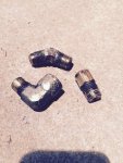
IMG_1825.jpg

All fittings out of the booster pump.

So tonight I'll be able to sleep.

The fuel fittings, hose, etc should be here tomorrow. As should some airpacks (and rebuild kits), a remote reservoir MC from Peashooter, and a gallon of DOT 5.
I couldn't find a reservoir I liked, so I designed this one, and will be machining it this weekend.
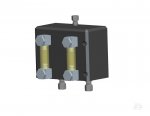
resvoir_assy.jpg
The upper fitting is to vent, but the vent line will have a quick release plug to fit into either the vent manifold (similar to Peashooter's) or into my pressure bleeder. The yellow things hanging off the front in the cad pic are sight tubes, so I won't have to open it to check it. (rated for 150 psi and compatible with DOT 5).

I also bought some wix filter brackets and (oddly), I can't stand the quality of the US made ones, but the Chinese one appears to be pretty good. All WIX brand. The China one will hold the first filter, which will be right by the tank, just as Rustystud did.

So... I also didn't like the way that the two filter brackets have to be serially linked (like the way Rustystud did), so I'll be machining a dual filter bracket shortly too, with all the cross plumbing done internally. I bought the overflow valve too, but I think I might integrate that into the housing as well... More on that after I finish the brakes and fuel lines.

ciao
lino
 

frank8003

In Memorial
In Memorial
6,426
4,985
113
Location
Ft. Lauderdale, Florida
Hey All,
The perfectionist side of me and the OCD side ganged up on me last night and I couldn't sleep because I was worried I couldn't get the 45 degree -6 AN fitting out of the inlet to the booster pump, and I really need that to be -8 AN so that it matches all the inlet line that I'm putting in.

So I dug into old posts and my heart sank when Clinto mentioned in one that he's never been able to get that one out... Great. I'm doomed.
I started with the feed for the flame heater (which I removed last night). Having read the recommendation to remove the 7/16 fitting and tube first, then use a socket with u-joint + wobble extension, I went to it. It worked well - from above. I started from below, with much less success. So that's out, and a nice hex drive plug in its place.

Then I wanted to remove both the inlet and outlet from the bottom of the booster pump... Gulp.
But, I recalled that I've been removing stuck things out of places you can't reach well or see, or both, for years (err, decades, now I guess). This one, you can see and touch at the same time! Boost of confidence, and away I went.

5 minutes later:
View attachment 540854

All fittings out of the booster pump.
So tonight I'll be able to sleep.ciao
lino
OK, Please tell what You did to get the fittings out of the booster pump.
Your multiple tens of years of un-stucking things would help.
I have the squashed tubing, nasty rubber hose to replace and have seen this stuff is not easy to get to. To be on the same page is fittings M, L + P those which you removed.
View attachment booster fuel injection pump HH TA013720.pdf
 
Last edited:

lino

Member
148
2
18
Location
Wake Forest, NC
OK, Please tell what You did to get the fittings out of the booster pump.

To be on the same page is fittings M, L + P those which you removed.
I took off fittings L, M, and N(assuming N is the compression fitting to feed flame heater).

And I'd have to say, it really wasn't that tricky. Oddly, mostly mental.
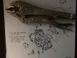
Open end wrenches don't fit/work on M or L. You can get a wrench on them, but the jaws deflect and mess up the fitting. So that's a no go.
L can't come off until M does because it can't rotate fully with M there.

So, M is first. The big deal (for me) was mentally committing to potential struggle and possibly doing damage...

That process generally follows this order (in a place where a torch isn't an option)
Stage 1: 10" Vise grips
Stage 2: if fitting breaks, remove enough to use screw extractor in bore.
Stage 3: If extractor breaks, chisel it out, and progressively drill out fitting, trying extractor at each stage.
Stage 4: Drill out fitting until only little pieces are left that can be chipped/picked out.
Stage 5: tap pipe threads slightly deeper to repair any damage from removal. - may take multiple taps each ground shorter to different lengths.
Note 1: Evaluate options and adapt at each stage...

Happily on both M and L, "stage 1" is all it took. With some care in the placement of the visegrips, and half-turn regripping, both fittings came off with no trouble and relatively little force. I managed to not even damage the AN threads on M.

So, it was a little anti climactic, but that's perfectly ok with me.
 

frank8003

In Memorial
In Memorial
6,426
4,985
113
Location
Ft. Lauderdale, Florida
I took off fittings L, M, and N(assuming N is the compression fitting to feed flame heater).

And I'd have to say, it really wasn't that tricky. Oddly, mostly mental.
Open end wrenches don't fit/work on M or L. You can get a wrench on them, but the jaws deflect and mess up the fitting. So that's a no go.
L can't come off until M does because it can't rotate fully with M there.

So, M is first. The big deal (for me) was mentally committing to potential struggle and possibly doing damage...

That process generally follows this order (in a place where a torch isn't an option)
Stage 1: 10" Vise grips
Stage 2: if fitting breaks, remove enough to use screw extractor in bore.
Stage 3: If extractor breaks, chisel it out, and progressively drill out fitting, trying extractor at each stage.
Stage 4: Drill out fitting until only little pieces are left that can be chipped/picked out.
Stage 5: tap pipe threads slightly deeper to repair any damage from removal. - may take multiple taps each ground shorter to different lengths.
Note 1: Evaluate options and adapt at each stage...

Happily on both M and L, "stage 1" is all it took. With some care in the placement of the visegrips, and half-turn regripping, both fittings came off with no trouble and relatively little force. I managed to not even damage the AN threads on M.

So, it was a little anti climactic, but that's perfectly ok with me.
A five stage plan and a evaluate/adaption note at each stage. I see what took years to formulate!
Did the fittings have that nasty plumbers putty/thread sealant on them?
I am getting ready (when the ground warms up) to follow "the plan"
vise grip IMG_4548.jpg
.
 

peashooter

Well-known member
1,038
205
63
Location
Hanover, minnesota
View attachment 540856
The upper fitting is to vent, but the vent line will have a quick release plug to fit into either the vent manifold (similar to Peashooter's) or into my pressure bleeder. The yellow things hanging off the front in the cad pic are sight tubes, so I won't have to open it to check it. (rated for 150 psi and compatible with DOT 5).

I'll be machining a dual filter bracket shortly too, with all the cross plumbing done internally. I bought the overflow valve too, but I think I might integrate that into the housing as well... More on that after I finish the brakes and fuel lines.

ciao
lino
Very interesting Lino! I really like that Reservoir, and the sounds of your dual filter bracket. Will you be machining them manually or on a CNC? I only ask because I bet you will have lots of interest from others in buying these things from you, so make a couple if you can. I'd be interested in the Dual filter bracket!
 

lino

Member
148
2
18
Location
Wake Forest, NC
Very interesting Lino! I really like that Reservoir, and the sounds of your dual filter bracket. Will you be machining them manually or on a CNC? I only ask because I bet you will have lots of interest from others in buying these things from you, so make a couple if you can. I'd be interested in the Dual filter bracket!
Happily, I have a CNC mill in my garage (that weighs within 1000 lbs of the deuce), so I'll be able to make multiples, once I have things sorted. And I'm kinda hoping there's additional interest... This hobby hasn't been cheap.
 

lino

Member
148
2
18
Location
Wake Forest, NC
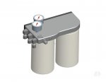
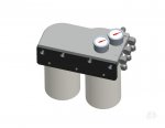
So it was a little too cold to convince myself to go outside tonight, and i was on a roll with the CAD tool, so I now have the first pass at a design for the fuel filter setup. I'll just start with teaser pics...

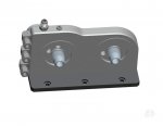
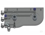
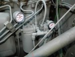
filter_assy1.jpgfilter_assy2.jpgfilter_assy3.jpgfilter_assy4.jpg

Hopefully the last one where I "glassed' the main body makes the inner plumbing a little more clear.

The goal was to keep all the fuel lines on the front side of the mount, closest to the IP.
The "IN", "OUT", and "RTN IN" are all set for DOT line. RTN to tank is -6AN
Pressure relief is internal and somewhat adjustable around 60psi
Pressure gauges read pre-filter and post-filter pressure.
It's designed to fit the same WIX filters as discussed in Rustystud's thread.
Main plate is 1" thick aluminium.
I hate pipe threads, and this had to be full of them...

Anyway, that's all for now...
 

rustystud

Well-known member
9,280
2,988
113
Location
Woodinville, Washington
So it was a little too cold to convince myself to go outside tonight, and i was on a roll with the CAD tool, so I now have the first pass at a design for the fuel filter setup. I'll just start with teaser pics...

View attachment 541017View attachment 541018View attachment 541019View attachment 541020

Hopefully the last one where I "glassed' the main body makes the inner plumbing a little more clear.

The goal was to keep all the fuel lines on the front side of the mount, closest to the IP.
The "IN", "OUT", and "RTN IN" are all set for DOT line. RTN to tank is -6AN
Pressure relief is internal and somewhat adjustable around 60psi
Pressure gauges read pre-filter and post-filter pressure.
It's designed to fit the same WIX filters as discussed in Rustystud's thread.
Main plate is 1" thick aluminium.
I hate pipe threads, and this had to be full of them...

Anyway, that's all for now...
If you can make that for a decent price I'll buy one ! I had to use what was available, and I don't like all the fittings either. Just a potential leaking point. I also like all the fittings on the front side. No more messing around the firewall. You might want to mount the pressure gauges vertically facing the fender. That way you just have to lower the side door and see what your pressures are without crawling on top of the engine.
 

lino

Member
148
2
18
Location
Wake Forest, NC
If you can make that for a decent price I'll buy one ! I had to use what was available, and I don't like all the fittings either. Just a potential leaking point. I also like all the fittings on the front side. No more messing around the firewall. You might want to mount the pressure gauges vertically facing the fender. That way you just have to lower the side door and see what your pressures are without crawling on top of the engine.
Decent price... Aye, there's the rub. I'll certainly be doing what I can. I need to do some tests to see if I can rigid tap pipe threads on the CNC. I usually hand tap those, but that will significantly affect the price. There are some pretty deep holes in this turkey too. Round 2 of design will be to tweak for manufacturability...

I like that thought on the gauges. I also don't like how the gauges are so close together on this one, and how the inlet gauge covers the inlet marking. I might look for a decent bottom exit gauge, instead of trying to put these gauges on the side edge facing the fender.
 

peashooter

Well-known member
1,038
205
63
Location
Hanover, minnesota
Decent price... Aye, there's the rub. I'll certainly be doing what I can. I need to do some tests to see if I can rigid tap pipe threads on the CNC. I usually hand tap those, but that will significantly affect the price. There are some pretty deep holes in this turkey too. Round 2 of design will be to tweak for manufacturability...
At work our machinists about never use taps, we just thread-mill all the threaded holes on the CNC but I never looked into seeing if you can thread-mill tapered threads. Do you know if that's possible?
 

lino

Member
148
2
18
Location
Wake Forest, NC
At work our machinists about never use taps, we just thread-mill all the threaded holes on the CNC but I never looked into seeing if you can thread-mill tapered threads. Do you know if that's possible?
I usually rigid tap smaller threads (that I have taps for) and threadmill larger threads (such as the 1"14 that will be used for the filters). I avoid pipe threads in general (I dislike the concept), so I've never had my CNC do them.
I know I can't single-point them because my CAM tool cant generate the expanding helix tool path. It's possible that if I can find a full length tapered thread mill (that's affordable), I could make the cut in one, non expanding, helical sweep.

Interesting problem. I'll look into it.
 

lino

Member
148
2
18
Location
Wake Forest, NC
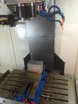
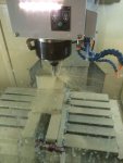
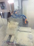
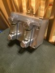
So I got the airpacks rebuilt, and just finished the remote reservoir last night. Here are some pics (before, during, and after) of the reservoir:
IMG_1862.jpgIMG_1865.jpgIMG_1867.jpgIMG_1868.jpg

Brake system should be ready to go in once it stops raining...

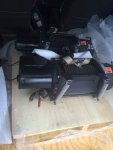
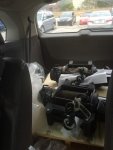
I also found a nice deal and picked these up yesterday:
IMG_1858.jpgIMG_1859.jpg
One fer the front and one fer the back...


That's all for this morning...
 
Last edited:
Do you have any an spot facers and cut straight thread then you can use a 815 an part and much less chance of buggering as no tapered threads just o ring seal on the aluminum part.

Are you profecient at g code?
 
Last edited:
Top