• Steel Soldiers now has a few new forums, read more about it at: New Munitions Forums!

  • Microsoft MSN, Live, Hotmail, Outlook email users may not be receiving emails. We are working to resolve this issue. Please add support@steelsoldiers.com to your trusted contacts.

IP timing questions

LuckyDog

Member
394
11
18
Location
Freedom, NH
Lots of developments.

BLUF:, I had the right shims, and I'm pretty sure I'm 180-bass-ackwards from correct timing.

I measured (4 times) the distance from the mounting surface to that flat machined surface on the cam, and after doing the math, came out to .014. so I measured the shims, and lo an behold I had a few different sizes to make the .014 I needed. then, to make it even better, I found where it was marked on the block, above where the IP mounts, where "014" is stamped clearly into the block. Nice.

Way to go!!!:smile:

So on to flow timing. I aligned the PC mark with the timing tab, the rockers were loose on the valve tips like someone else said, and according to the manual, "one lobe is pointed out and 45 degrees down." which it appeared to be. which one, you ask? not the valves corresponding to cylinder #1, I figured out later. so I realized that my PC mark was lining up halfway through the injection cycle on #1, or during part of #3. so I'm more like 90 degrees out. just enough to be annoying. so I'm gonna set it up again and try to crank tomorrow. just wanted to share the info. I felt a little defeated at first, but now that I know what I did wrong, I know where to start tomorrow.

Later,
Josh
I searched the -12 and -34 manuals. I couldn't find "one lobe is pointed out and 45 degrees down." Where does it say that? Some other manual???:confused:

Did you use the 1/8" rod in the timing hole and verify that cylinder one's rocker arms are loose? (See page 7-38 of the -34 manual) You can do this with the pump mounted on the engine. I just used a 5/8" deep well socket and rotate the crank until the rod pops into the IP timing hole. Either cylinder one or four rocker arms should be loose. The PC mark should be very close to the pointer. There is some slop in the gears so it won't be perfect.

Hard to believe the flywheel would mounted 90° out.... Never mind, I was in the service, quite possible, not likel, but possible.

Did you install the pump IAW paragraph f. "Install (Method 1)" on page 7-38 of TM 5-6115-585-34?

Keep up the good work, you have made a LOT of progress. Your almost there.:grd:
 

helomedic1171

Member
205
12
18
Location
Dacula, GA
I used the -34 manual AND the 7-page bulletin from AMBAC someone posted up earlier; the latter is where the lobes pointing different directions came from. and yes, the rockers were loose and the timing pointer was on PC when i mounted it. i used a drill bit (the shank, not the fluted portion) as my "rod" to hold the pump gear still. I think the flywheel is properly mounted, but what causes me to suspect that I'm significantly off-time is that when i do what the manual says, I "move the blower wheel counterclockwise about 1-inch, then begin turning the blower wheel clockwise until fuel stops flowing from the #1 fuel line" the flywheel reaches "PC" when the #3 hole is pushing fuel. is there more than one place in the combustion cycle where both rockers are loose? if not, then I may not be in terrible shape. also, do I plug the return line and the other three cylinders? I'm using an IP originally from an 002A, so I just left the two caps on. I'm thinking maybe I cap off the return port and the #3 cylinder port and double check my timing position. I'm closer, just not close enough to see where i need to be headed. I'm going to put on my coveralls in a minute... maybe the horseheads on my twin Cav shields will whisper nuggets of wisdom in my ear. or maybe the generator will see the similar color green in the picklesuit's fabric and think we're kindred spirits. Or maybe one of you guys will come up with another pearl like this one:
Either cylinder one or four rocker arms should be loose. The PC mark should be very close to the pointer. There is some slop in the gears so it won't be perfect.
that makes me say "EUREKA!!" and start peeing excellence. however it happens, I'm getting more motivated by moment.
 
Last edited:

helomedic1171

Member
205
12
18
Location
Dacula, GA
Also, I'm trying to use white on the background, because I know a lot of you guys have difficulty reading posts without contrasting font/background color. hope it helps. if not, I can change it to something else.
 

LuckyDog

Member
394
11
18
Location
Freedom, NH
I used the -34 manual AND the 7-page bulletin from AMBAC someone posted up earlier; the latter is where the lobes pointing different directions came from.

Ok, thanks for that intel.

and yes, the rockers were loose and the timing pointer was on PC when i mounted it. i used a drill bit (the shank, not the fluted portion) as my "rod" to hold the pump gear still. I think the flywheel is properly mounted, but what causes me to suspect that I'm significantly off-time is that when i do what the manual says, I "move the blower wheel counterclockwise about 1-inch, then begin turning the blower wheel clockwise until fuel stops flowing from the #1 fuel line" the flywheel reaches "PC" when the #3 hole is pushing fuel. is there more than one place in the combustion cycle where both rockers are loose? if not, then I may not be in terrible shape.

They will only be loose during compression and power strokes. (Only once per two revolutions) The PC mark will put cylinders 1 and 4 near TDC so only one will have both rockers loose. (and we all agree cylinder #1 is closest to the blower end right?:D)

also, do I plug the return line and the other three cylinders? I'm using an IP originally from an 002A, so I just left the two caps on. I'm thinking maybe I cap off the return port and the #3 cylinder port and double check my timing position.

Now that makes me wonder.... If the two orignal caps are still on the pump me thinks your #3 is actually #4. The firing order is 1-2-4-3. Are you counting the ports 1-2-3-4?

I'm closer, just not close enough to see where i need to be headed. I'm going to put on my coveralls in a minute... maybe the horseheads on my twin Cav shields will whisper nuggets of wisdom in my ear. or maybe the generator will see the similar color green in the picklesuit's fabric and think we're kindred spirits. Or maybe one of you guys will come up with another pearl like this one:
that makes me say "EUREKA!!" and start peeing excellence. however it happens, I'm getting more motivated by moment.
Make sure you -> "Set throttle lever on injection pump to wide open or up position (compress stop solenoid plunger spring or remove stop solenoid assembly)." That is really important.


Also important: "The point at which fuel stops flowing from Number 1 cylinder fuel delivery line is the injection pump port closing point. Stop rotation of engine at exactly the port closing point (l-2 drops in 5-10 seconds)"

Don't know if fuel will flow from the other ports. My experience doing the flow timing method was on a busted IP on an 002A. It is REAL easy to mount the pump 180° out.

Did the horses wisper to you yet???
 

helomedic1171

Member
205
12
18
Location
Dacula, GA
yes, they tell me I'm probably 180 out, so I'm starting over using your pointers. also, I adjusted the timing pointer on the flywheel (according o the figure in the manual) and I also noticed a pointer on the blower wheel end. the AMBAC bulletin shows this pointer as the one to use. thoughts? is it possible that my blower and flywheel aren't aligned? I've been using the flywheel end to check for "PC". I'll be checking for markings on the blower wheel momentarily, once I mark where "PC" is on the side to make it easier to see when it comes around. and you might be right about #1 and 4 versus #1 and 3.... I'm counting 1-3 and 2-4 like a chevrolet... sumbitch, you ARE right... it's #1 and #4, not 3 like i previously posted. k. back to tinkering.

PM inbound.
 

LuckyDog

Member
394
11
18
Location
Freedom, NH
yes, they tell me I'm probably 180 out, so I'm starting over using your pointers. also, I adjusted the timing pointer on the flywheel (according o the figure in the manual) and I also noticed a pointer on the blower wheel end. the AMBAC bulletin shows this pointer as the one to use. thoughts?

I used the one on the flywheel.

is it possible that my blower and flywheel aren't aligned?

Don't know... Never looked

I've been using the flywheel end to check for "PC". I'll be checking for markings on the blower wheel momentarily, once I mark where "PC" is on the side to make it easier to see when it comes around. and you might be right about #1 and 4 versus #1 and 3.... I'm counting 1-3 and 2-4 like a chevrolet... sumbitch, you ARE right... it's #1 and #4, not 3 like i previously posted. k. back to tinkering.

PM inbound.
While there are a lot of similarities between the Civy Onan and the MEP-Onan, There are some very significant differences.
The TM's are very thorough and (mostly) correct. I suggest using the TM methods over the ambac and civy Onan manuals. I have 'em all, but use the TM mostly.

There is a method in the TM on how to adjust the pointer and PC mark. I haven't tried it, don't have the tools. Somebody here on SS has done it, or done it on a similiar motor. Involves dropping the valve into the cylinder head.:!: Maybe I should say, dropping the valve onto the piston?
 

helomedic1171

Member
205
12
18
Location
Dacula, GA
yeah. no thanks. I just aligned the pointer hashmarks according to the figure in the TM and went with that. I also made a sharpie mark on the blower wheel where PC is when both rockers are loose, and that makes it easier to spot when I'm getting close to the mark. I've stopped using the AMBAC manual this go-around, because it was confusing me more in the first place. I've got the pump back on the block, the supply hooked up, and I've got a plug for the return port. I'm nearly ready to try again.
 
Last edited:

Speddmon

Blind squirrel rehabiltator
Super Moderator
Steel Soldiers Supporter
4,640
28
38
Location
Cambridge, Ohio
I doubt that the flywheel and blower wheel are out of alignment. USUALLY the flywheel will have one hole that is just a little off of the bolt pattern so you can only get it on one way (This is to keep timing marks in the proper locations). And the blower wheel is Keyed to the shaft so it can only go on in one location as well.
 

helomedic1171

Member
205
12
18
Location
Dacula, GA
Blower wheel has no markings, and you are right - my flywheel markings are correct. Lucky and I talked over the phone at length, and we noticed something weird. I'll give you as good a play-by-play as I can remember:

I reset the engine to the PC mark, verifying that A) both rockers were loose on #1 B) this event was preceded by the intake valve closing and the compression stroke beginning. when PC aligns with the timing tab, we are in the midst of the compression stroke.

Next, I reset the IP with a small drill bit (my 1/8 rod) to hold the face gear in place while I slid the pump on. I then connected the supply, return, and #2, #3, and #4 injector lines.

I then disconnected/removed the solenoid to allow WOT from the IP, and pulled the linkage to hold the throttle in place.

I disconnected #1 injector line from the injector, and loosened it from the pump. I oriented it so that it pointed into an empty jerry can, and tightened it at the pump. I primed the system, and saw fuel immediately spurt from the line.

I positioned my socket wrench and turned it counterclockwise 1 inch as the TM calls for in step (d) on page 7-40. I then followed step (e), which was "rotate blower wheel clockwise until fuel flows from the Number 1 cylinder fuel line". REMEMBER - Fuel is already flowing, even after I rotated the 1 inch CCW.

As I rotated clockwise, I watched the fuel line. when i reached about 90 degrees (almost a 1/4 turn) of the blower wheel, fuel stops. the "PC" mark is no where to be found in the hole. I don't even have the "A" or "B" marks or any tick marks.

if I turn the wheel to the point jsut before fuel starts flowing, I'm about 90 degrees before the "PC" mark. if I follow through til the fuel stops, I'm about 180 degrees of total travel, with "PC" being right about in the middle.

Guys, I'm pretty lost on this - I'm setting it up right, I removed the delivery valve spring from the pump, I put the timing screw back in the hole after I installed the pump and bolted it down, I have good flow in every line, to include return and all 4 injector lines... what gives? is the problem that I used an 002A pump? I have an 003A pump on the shelf, but since the manual calls for using a # 12 or "M" button, and the 002A pump had that button in it instead of a #1 or A like the other pump did, I used it. I even made sure to remove the capped fittings and replace them with the correct fittings for the injector lines from the 003A.

Thoughts?
 
Last edited:

Speddmon

Blind squirrel rehabiltator
Super Moderator
Steel Soldiers Supporter
4,640
28
38
Location
Cambridge, Ohio
Pull the pump back off and inspect the cam and lobe VERY closely. Something is amiss. Even with the wrong button you shouldn't need to go that far to get the fuel to stop. Are you positive the cam isn't broken and slightly spinning? If they look good, next I would have to question the pump itself...are you sure it was built properly? Was it a straight pull from a good generator or a rebuild? I'm not 100%sure, but there are marks inside the pump on certain components to make sure they are assembled properly. Maybe try to pull all of the lines off and see if any of them act properly by starting at the PC mark and going through the rotations again.
 

helomedic1171

Member
205
12
18
Location
Dacula, GA
If by the cam you mean the camshaft in the engine, yes, it's working as it should. as for anything inside the pump, not sure - I got two pumps, one pulled off of an -002A (the one I'm using right now) and one from an 003A (the one that sits on my shelf for a spare). the 002A looked nicer and cleaner, so i used it, plus it had the #12 button that the TM calls for when doing Flow-timing. is there any difference between 002A and 003A pumps besides the two plugged ports on the 002A pump? are the inner workings changed at all? I'm thinking about pulling the #12 button from the pump, putting it in the 003 pump I have, and trying that one to see if there's any difference.
 

helomedic1171

Member
205
12
18
Location
Dacula, GA
More updates... the pumps are identical, in case anyone was wondering. I took both apart - good thing, too, because the -003A pump had a broken alignment tab (alignment cam?) and the gear was spinning, but nothing was pumping. the 002A pump, which I've been using all this time, turns beautifully, and the plunger is free and slides easily. It was a little hard to move and felt sticky, but working with it, the plunger loosened up and now slides nicely, whereas the 003A pump plunger had to be loosened with a flat-tip screwdriver. so, I put both back together, and now the 002A pump (which is now configured for an 003A) is back on the bench ready to be re-installed yet again. the engine is on "PC", and we're ready to try this one more time. I'm hoping with the freed up plunger, the results will make more sense. I'm assuming once I prime the system, I still have to leave the fuel pumps running, yes? I'm not supposed to shut them off after i get some fuel pressure, because the TM doesn't tell me to shut them off.

any other ideas, I'm all ears. here's to a more favorable outcome tomorrow.
 

LuckyDog

Member
394
11
18
Location
Freedom, NH
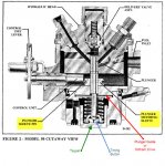
IP parts recognition training

Schooling time.....

IP Cutaway view.jpg

Let's make sure we aren't confusing "Tappet" and "Timing Button". It wasn't completly clear to me until I rebuilt my pump.

The red arrow points to the plunger guide. Sometimes called an "Oldham Drive". That is what most likely broke in your pump off the 003A. Very common part to break. (Was actually designed to be a weak link to save the rest of the pump from damage)

Manuals say the plunger metering sleeve has a dot on one side. See pages 6 & 7 of : http://www.ambac.net/images/Diese_Fuel_Injection_Pump.pdf .
That is a good reference for re-assembly. Pay attention to the "Caution" note on page 7.

This link: http://www.ambac.net/images/9540A.pdf has better pictures of all the parts in the pump and assembly order. If your pumps are missing any of these parts you can call 800-628-6894 (http://www.ambac.net/) to get them.

If the timing button is there, maybe the the control unit is not correct. As stated in the caution note, it will turn 360° with the retainer plate off. The retainer plate has the adjusting screw that limits WOT setting.


:popcorn: Waiting on results.....
 

helomedic1171

Member
205
12
18
Location
Dacula, GA
The tappet looks like the bottom of a flat-tappet lifter in a gasoline engine, the button is the little piece inside, on top of the spring retainer that has it's own small lock ring that hold it on top of the retainer. it has a small number punched on the side like "1" or "12".

That's really informative - it was in fact the plunger guide/oldham drive that broke. makes me happy that the pump isn't totally FUBAR. anyone know where to get a new one besides calling AMBAC?

And the button is in the pump, where it's supposed to be on the bottom of the lower spring guide. the control unit does turn 360 degrees now that I've freed up the metering sleeve. I really think everything is in order now and the pump should work as it's supposed to. I'm going to go out and retry the flow timing one more time and see what happens. But seriously, the only thing I could see wrong was that the control unit/lever seemed to stick, which meant the metering sleeve wasn't functioning properly inside as a result. we'll see what happens shortly.

LuckyDog, thanks for the diagrams, I saved them all for future reference.

details to follow....
 
Last edited:

helomedic1171

Member
205
12
18
Location
Dacula, GA
unstuck plunger and cleaned out IP fixed it. when I flow timed it, the #12 was exactly the right one. I hooked everything back up, cranked it, and brought it up to 60 Hz as soon as I heard a grumble or two of life. she purred like an old housecat, even better than my Dad's genset did. I'm super excited. hit the outlets and the output lugs, and I'm getting voltage and a true 60-ish cycles, it varies between 60.1x to 61.0x once it's warm and the gauge is pretty darn accurate, registering nearly the same on the gauge as I had on my Fluke meter. still have to load test it, so that's my next task, but all thus far, I'm stoked and extremely satisfied. thanks for all the hard work and help, guys. I learned a LOT.
 

helomedic1171

Member
205
12
18
Location
Dacula, GA
IMAG0140.jpg
The Louvres open!!!!
IMAG0139.jpg
my gauges right after starting her up.
IMAG0138.jpg
and this is the stamp I found to identify the shims, it's right above the mounting surface for the IP.

here's a link http://www.steelsoldiers.com/showthread.php?95218-About-to-pick-up-my-MEP-003A to the original thread where I brought her home, with the "before" pictures. "after" pictures to follow.

The gauge panel is the biggest difference, I have Jerry to thank for that! I also did some painting too.
 
Last edited:

Speddmon

Blind squirrel rehabiltator
Super Moderator
Steel Soldiers Supporter
4,640
28
38
Location
Cambridge, Ohio
Awesome. Another success story!!!!! Congrats. I remember when you brought it home and had some concerns about not having a pump and possibly not having the shims. I'm very glad to see that you got it running.
 

helomedic1171

Member
205
12
18
Location
Dacula, GA
thanks. I remember a couple of guys were concerned I may have gotten a total heap, and rightfully so - I was missing nearly everything that could be gotten by a vandal with tools and time. but, I got her together, and I posted up some "after pictures" in the original thread, which I linked to above. check them out, it's pretty cool to see how much different it looks. even my wife was impressed with the progress, and she was really surprised to see just how much different it looks when compared to the original pics and screen captures.
 

Speddmon

Blind squirrel rehabiltator
Super Moderator
Steel Soldiers Supporter
4,640
28
38
Location
Cambridge, Ohio
You think she's impressed now....wait until you have it running and the rest of the neighborhood is as black as coal. Yet, you'll still be living life normally :smile:
 
Top
AdBlock Detected

We get it, advertisements are annoying!

Sure, ad-blocking software does a great job at blocking ads, but it also blocks useful features of our website like our supporting vendors. Their ads help keep Steel Soldiers going. Please consider disabling your ad blockers for the site. Thanks!

I've Disabled AdBlock
No Thanks