• Steel Soldiers now has a few new forums, read more about it at: New Munitions Forums!

  • Microsoft MSN, Live, Hotmail, Outlook email users may not be receiving emails. We are working to resolve this issue. Please add support@steelsoldiers.com to your trusted contacts.

Kinda got carried away..... M1028 rebuild

Sharecropper

Well-known member
Steel Soldiers Supporter
1,836
987
113
Location
Paris KY
With all that $$ invested, I’m surprised you don’t have the manifold intake covered to prevent any FOD from getting inside.
The manifold is not bolted down yet. The GEP tape is still covering the openings in the heads. I still need to connect the flexible fuel line from the FFM to the IP and make one last adjustment to the TV cable, and then I’ll be ready to remove the factory tape and bolt her down. At that time I will tape over the breather hole to prevent anything from falling in there. Good catch by the way.
 

cucvrus

Well-known member
11,473
10,427
113
Location
Jonestown Pennsylvania
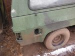
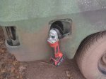
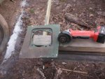
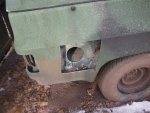
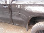
DSCF5892 (1).jpgDSCF5893 (1).jpgDSCF5894 (1).jpgDSCF5895 (1).jpgDSCF5896 (1).jpgAfter the phone call I went out and cut the fuel door opening out of the 1/4 panel. This M1009 will never be back on the road. It had 13 K miles and I bought it as residue. That cordless Milwaukee is an awesome tool. I was sure you want the CUCV one. The Z71 was a different size. You need the M1008 filler neck , hoses and fuel cup. The cap may be the only thing I don't have extra. But I do somewhere. I know you like new. Can you find a new cap with nice lettering?
 

Sharecropper

Well-known member
Steel Soldiers Supporter
1,836
987
113
Location
Paris KY
View attachment 754449View attachment 754450View attachment 754451View attachment 754452View attachment 754453After the phone call I went out and cut the fuel door opening out of the 1/4 panel. This M1009 will never be back on the road. It had 13 K miles and I bought it as residue. That cordless Milwaukee is an awesome tool. I was sure you want the CUCV one. The Z71 was a different size. You need the M1008 filler neck , hoses and fuel cup. The cap may be the only thing I don't have extra. But I do somewhere. I know you like new. Can you find a new cap with nice lettering?
Rick - thanks for getting the fuel door assembly for me. It will be the finishing touch for the factory auxiliary tank install. Yes I think I know where a NOS fuel cap is. Now all I need to decide is a source for the auxiliary tank. Do you have any experience with those LMC tanks? Or would you rather look for a clean used one? Or do you know another source for a new tank? Any help you can provide will be appreciated. Mike
 

Sharecropper

Well-known member
Steel Soldiers Supporter
1,836
987
113
Location
Paris KY
Any new progress Mike?
Yes just a little. I've been extremely busy the past few months helping manage my wife's company, but have almost completed the mock-up of the custom aluminum bracket to hold the Spinner oil filter. I had to draw the bracket to scale and then custom bend 3/16" 6061 aluminum to fit. I used a 3/4" x 1" 6061 solid aluminum bar to fabricate the bottom mount, which itself mounts into two of the valve cover bolt holes. The Spinner will receive its oil pressure from the front turbo port (which will not be used because I am not going to turbo the engine). I plumbed the turbo port with rigid brass piping to a stainless aircraft on-off valve just above the crossover. From that valve to the Spinner I will fabricate -4AN flexible hose which will snake around the air cleaner. When in operation at 35psi, the Spinner will spin inside the vessel at approximately 6000 rpm and remove all impurities from the oil via inertia. All impurities in size down to sub-micron will be forced to the inner wall of the spinning vessel, where they will accumulate. The cleaned oil will then drain down into the valve cover via gravity. During normal maintenance the outer vessel of the Spinner can be quickly removed and scraped out and cleaned. For those readers who do not know, a germ's body is 1 micron wide. A normal factory oil filter will remove particles and contaminents in size down to approximately 20 micron. The engine gaps between bearing surfaces range in size from 5-10 micron, which means the factory oil filter allows particles and impurities smaller than 20 micron to pass through to the bearing surfaces. As the factory oil filter traps impurities and contaminents and becomes less efficient, the micron size increases. The Spinner will remove these smaller contaminents, and even remove the carbon blow-by to keep the oil honey-colored. Once I get the engine installed and all systems in operation, I plan to take regular oil samples at 1000-mile intervals to monitor the efficiency of the Spinner. It should be interesting. Here are a few photos -
 

Attachments

ken

Active member
Steel Soldiers Supporter
2,479
25
38
Location
Houston Texas
Good work Mike that looks awesome. You are 100% correct on the centrifuge filter. They work great. If you ever search oil filters you will be shocked how bad of a job they actually do. Very few companies will even tell you what their beta ratio is. Much less how many microns they filter. That engine should last forever with oil that clean.
Yes just a little. I've been extremely busy the past few months helping manage my wife's company, but have almost completed the mock-up of the custom aluminum bracket to hold the Spinner oil filter. I had to draw the bracket to scale and then custom bend 3/16" 6061 aluminum to fit. I used a 3/4" x 1" 6061 solid aluminum bar to fabricate the bottom mount, which itself mounts into two of the valve cover bolt holes. The Spinner will receive its oil pressure from the front turbo port (which will not be used because I am not going to turbo the engine). I plumbed the turbo port with rigid brass piping to a stainless aircraft on-off valve just above the crossover. From that valve to the Spinner I will fabricate -4AN flexible hose which will snake around the air cleaner. When in operation at 35psi, the Spinner will spin inside the vessel at approximately 6000 rpm and remove all impurities from the oil via inertia. All impurities in size down to sub-micron will be forced to the inner wall of the spinning vessel, where they will accumulate. The cleaned oil will then drain down into the valve cover via gravity. During normal maintenance the outer vessel of the Spinner can be quickly removed and scraped out and cleaned. For those readers who do not know, a germ's body is 1 micron wide. A normal factory oil filter will remove particles and contaminents in size down to approximately 20 micron. The engine gaps between bearing surfaces range in size from 5-10 micron, which means the factory oil filter allows particles and impurities smaller than 20 micron to pass through to the bearing surfaces. As the factory oil filter traps impurities and contaminents and becomes less efficient, the micron size increases. The Spinner will remove these smaller contaminents, and even remove the carbon blow-by to keep the oil honey-colored. Once I get the engine installed and all systems in operation, I plan to take regular oil samples at 1000-mile intervals to monitor the efficiency of the Spinner. It should be interesting. Here are a few photos -
 

roddog

New member
25
0
1
Location
sunnyvale , ca
Now, this is my kinda guy.. I'm sorry for offending any purists. But this is the only vehicle in the people's republic of California, that can be a clean slate. No gov laws, no smog, low reg fees.
 

Keith_J

Well-known member
3,657
1,319
113
Location
Schertz TX
Now, this is my kinda guy.. I'm sorry for offending any purists. But this is the only vehicle in the people's republic of California, that can be a clean slate. No gov laws, no smog, low reg fees.
Free from all the stuff determined by the state of cancer to cause California ;)
 
I found I had to modify a 1009 fuel intake system (green painted one) to meet the tank ports on the right side. The M1008 was too short (first attempt pic) and getting OEM military hoses to join them without kinking was "fun". I love T-bolt clamps...

I also had to invert the fill door to put it on the other side and drill new holes for the fuel intake to mount to (no biggie, just a 180 degree mod)
 

Attachments

Last edited:

Sharecropper

Well-known member
Steel Soldiers Supporter
1,836
987
113
Location
Paris KY
Any new progress Mike?
Well after several months hiatus helping manage my wife's company, I am finally ready to get back to work on my P400 / 700R4 build and continue this rebuild thread, which has now gone on for nine (9) years.

The first order of business was to bolt down the new open-plane intake manifold. Since it had been a while since I had even looked at the engine on the stand, I decided to inspect things under the intake to make sure everything was tight and the way it was supposed to be. However the more I looked at that 1/4" rubber fuel line running from the fuel filter to the pump, the more i hated it. Having learned that one of the causes of rough starting/running was a leaky fuel line which sucks air into the fuel, and considering the fact that to repair a possible future leak in this section of hose would mean removing the intake, I decided to upgrade the fuel line to a -06 AN line and hose.

I removed the 1/4" rubber hose and factory ferrell from the injection pump. Then I removed the fuel filter and twisted out the pressed-in outlet ferrell. I then drilled and tapped the fuel filter to accept a 1/4" NPT pipe thread, and ordered the appropriate AN fittings and hose from Summit Racing. The inlet ferrell fitting in the injection pump is a 7/16"-24 inverted flare, and I needed a special fitting to transition from this to a -06 AN. Luckily, Leroy offers this fitting, so I ordered one from him (Thanks Leroy!). I then fabricated the proper length of -06 AN hose with the appropriate fittings and installed the assembly without a hitch. All fittings were torqued properly and now I don't have to worry about future leaks. Next step - install the intake.
 

Attachments

richingalveston

Well-known member
1,715
120
63
Location
galveston/Texas
glad to here you can get back to work on it. I am ready to see the engine back in the truck.
I was going to change the fuel line on mine to be similar to yours, my fuel filter is in stock location. but I did not because it would be next to impossible to get it loose without removing the intake. With the hose clamps you can stick an extended socket in there and loosen the clamps. Very difficult to loosen it with a wrench. It might come off with a crows foot reaching in from the firewall direction but that would be difficult and I am not sure you can spin a crows foot around due to the injector lines.

I like the AN fittings and how yours turned out.
good luck with the remaining work
 

nattieleather

Well-known member
1,882
143
63
Location
Cleveland, OH
I've read through the whole thread and I seem to be missing one thing. Where did you get the TV cable and corresponding brackets for the diesel? Also just wondering why you didn't go turbo with the bigger motor? Thank you in advance for your reply and your work is great and inspiring to me.
 

Sharecropper

Well-known member
Steel Soldiers Supporter
1,836
987
113
Location
Paris KY
I've read through the whole thread and I seem to be missing one thing. Where did you get the TV cable and corresponding brackets for the diesel? Also just wondering why you didn't go turbo with the bigger motor? Thank you in advance for your reply and your work is great and inspiring to me.
The TV cable bracket for a 6.2 diesel engine is rare, however can be obtained through Ebay occasionally. Sometimes a fellow Steel Soldier member will have one for sale. I purchased mine by watching Ebay on a daily basis. If I remember correctly, I paid $100 for mine. The TV cable is still available on Ebay as well. It is GM part #25515599, 36.1 overall length, cable code FK.

I chose NOT to turbo the P400 for several reasons. I have owned many GM diesel trucks since 1985 and every one of them was turbo's. While a turbo indeed adds great power, it also adds substantial heat. Think about it - a law of nature indicates than whenever air is compressed, the heat within it as also compressed and increases. So a turbo takes in ambient temperature air and compresses it, which makes it hotter. It then sends that hot air into the intake and engine, which increases the engine temperature. The turbo gets it's power from hot exhaust gases, which sometimes can reach 800-900 degrees. This in itself increases the temperature of the turbo housing, which then transfers some of that heat into the intake air, thereby making it even hotter. It is an escalating cycle of producing heat.

All a turbo is doing is increasing the amount of air into the cylinders prior to fuel injection. This, in effect, simply increases the compression ratio and provides more volume for more fuel to be burned, thereby producing more horsepower.

If my goal was to produce mucho horsepower, I would have opted to install a GM crate LS engine. Instead, I wanted a cool-running, free breathing engine which would bolt up without major modification. When a brand new P400 in the crate came available, I bought it. What has been surprising through this whole process is how everything which was on the 1984 6.2 engine has fit on the 2018 P400 6.5. I mean everything. Even the idiot light sensors from the 6.2 screw right into matching orfices in the P400.

I purchased my first truck 54 years ago. I have learned that the killer of engines is Heat and Dirt. That is why I am not installing a turbo, and also why i AM instaling a centrifical oil filter system. I did not purchase the ceramic coated headers to produce more horsepower, but instead, to get those hot exhaust gases out of the engine as quickly as possible. I want cool air going into the engine, and those hot exhaust gases out as fast as possible.

The P400 is rated at 225 horsepower non-turbo. I had Hucksdorf Diesel set my new DB2891-4911 mechanical pump at 200 horsepower. I want to see how that feels in front of my 700R4 before I fool with the fuel screw. If it runs smooth with no smoke and stays cool, I will leave it as it is.

Speaking of my 700R4, I made the decision to use a 700R4 because it is a "dumb" unit without any electronics. Same reason I wanted a "dumb" injection pump and a "dumb" fuel pump. Same reason all my new gauges will be 'dumb" mechanical instead of electric operation. If our world ever transgresses into chaos, my truck will crank and run, while those electronic vehicles will not. My 700R4 was built by Bowtie Overdrives in California and is rated at 450 HP and 450 FPT. I think it will handle those 200 horses from the P400 just fine.

Thanks for your post and I hope you continue following my thread. Let me know if I may assist you in any way.
 

Sharecropper

Well-known member
Steel Soldiers Supporter
1,836
987
113
Location
Paris KY
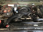
Before bolting down the intake, I decided to test-fit the Spinner centrifugal oil filter on its custom bracket and fabricate the braided oil supply line. Because I will not be installing a turbo, I chose to supply the Spinner with pressurized oil from the turbo oil port on the front of the passenger-side head area. I will wait to permanently install this filter until the engine has been installed, due to the close proximity of the filter housing to the hydro-boost. Sure don't want to ding it during install.
 

Attachments

ken

Active member
Steel Soldiers Supporter
2,479
25
38
Location
Houston Texas
Mike, I just read your reasons about why you opted not to use the turbo. I have to say I could not agree with you more. I have a very similar set up in my 1028A1. I have a rebuilt GM 6.5 from a 94 K2500. I too removed the turbo and am running the same intake. I have a 4911 pump also that I didn't turn down. Although I don't have a set of Stans headers, I was waiting to see how well they worked out for you. I did replace the exhaust with 3 inch and turned it down just before the rear axle. With this setup it will easily spin the rear tires at a red light. It tows my tractor with ease and provides enough power for my needs. I am using a 180 deg Mildon thermostat from summit to keep any worries of coolant boiling at the rear of the block at bay. I made a ram air for the intake so It would get fresh cooler air straight from the front and not from the engine compartment. For a CUCV it's been very reliable. IMG_0417.jpg
 

Sharecropper

Well-known member
Steel Soldiers Supporter
1,836
987
113
Location
Paris KY
Ken -
I’m running that same ram air on my 6.2 now and it definitely improves performance. The breather and hose will be used on the P400.
I also plan to install -04 lines from the rear coolant plates routed to the HMMWV crossover to help the heat dissipation of those rear cylinders. I’m going to fabricate those lines myself instead of buying the Paradox kit. I’ll photo document all this as it happens.
I’ve decided to add the Vintage Air kit. I ordered the compressor brackets yesterday from a small mom and pop machine shop in Ft Worth. I’ll photo document this also.
Mike
 
Top
AdBlock Detected

We get it, advertisements are annoying!

Sure, ad-blocking software does a great job at blocking ads, but it also blocks useful features of our website like our supporting vendors. Their ads help keep Steel Soldiers going. Please consider disabling your ad blockers for the site. Thanks!

I've Disabled AdBlock
No Thanks