• Steel Soldiers now has a few new forums, read more about it at: New Munitions Forums!

  • Microsoft MSN, Live, Hotmail, Outlook email users may not be receiving emails. We are working to resolve this issue. Please add support@steelsoldiers.com to your trusted contacts.

LBCD replacement due to loose studs. CARNAGE!!

87cr250r

Well-known member
1,267
1,988
113
Location
Rodeo, Ca
In my fleet I run 25 amp float only chargers on 8D batteries (currently downsizing to group 31) for engine starting an ECM power. As long as you are not starting frequently you don't need much charger to keep a battery charged. Even a Caterpillar 3500 series engine with electronic injectors only pulls 10 amps max when running.

I despise the fancy electronic chargers with their bulk and absorption charging cycles. I don't see any benefit to my operation and the electronic chargers fail frequently. Mag-Amp only for me.

This is the good stuff here: https://www.lamarchemfg.com/products/a12b.html
 

Lostchain

Well-known member
Steel Soldiers Supporter
284
586
93
Location
Portland, OR
Sales hype? The cautions in their troubleshooting manuals clearly contradict this…
Interesting, Niehoff seems to have a patent to do what you are saying their alternator cant do......


FIELD OF INVENTION
This invention is related to a control device for a generator, including a system and method, wherein the control device uses a conductor embedded in the generator to measure the total generator output current and operates to limit and/or cease the output current according to said measurement. The control device may be used in conjunction with the generator for improved monitoring, diagnostics, and control functions. This invention further relates to a generator incorporating a conductor which comprises a process-controlled geometric shape.
 

MatthewWBailey

Thanks for this site. My truck runs great now!
Steel Soldiers Supporter
816
1,491
93
Location
Mesa Colorado
Interesting, Niehoff seems to have a patent to do what you are saying their alternator cant do......


FIELD OF INVENTION
This invention is related to a control device for a generator, including a system and method, wherein the control device uses a conductor embedded in the generator to measure the total generator output current and operates to limit and/or cease the output current according to said measurement. The control device may be used in conjunction with the generator for improved monitoring, diagnostics, and control functions. This invention further relates to a generator incorporating a conductor which comprises a process-controlled geometric shape.
I think it's doing it but as an analog controlled device, there's a curve. The internal "control device" is simply a shunt, that shunt voltage feeds the VR. A 5% tolerance on the analog circuit could cause a 120A output before major voltage drop. & Idk what their shunt circuit tolerance is. Analog controls work, they just have wide tolerances compared to digital systems, and those tolerances widen over usage time.

Part of their description says...
"Preferably, the control device limits the total electrical output current when the electrical potential is within a predetermined range, for instance V1 and V2, and ceases said output current when the electrical potential is greater than V2."

So it works, "preferably". I'm taking my LBCD apart tomorrow to compare to the generals'
 

Lostchain

Well-known member
Steel Soldiers Supporter
284
586
93
Location
Portland, OR
I think it's doing it but as an analog controlled device, there's a curve. The internal "control device" is simply a shunt, that shunt voltage feeds the VR. A 5% tolerance on the analog circuit could cause a 120A output before major voltage drop. & Idk what their shunt circuit tolerance is. Analog controls work, they just have wide tolerances compared to digital systems, and those tolerances widen over usage time.

Part of their description says...
"Preferably, the control device limits the total electrical output current when the electrical potential is within a predetermined range, for instance V1 and V2, and ceases said output current when the electrical potential is greater than V2."

So it works, "preferably". I'm taking my LBCD apart tomorrow to compare to the generals'
When you say its an analog controlled device, what do you mean specifically? The Voltage regulators are microprocessor controlled. Do you mean that the microprocessor is relying on an analog current sensor?
 

MatthewWBailey

Thanks for this site. My truck runs great now!
Steel Soldiers Supporter
816
1,491
93
Location
Mesa Colorado
When you say its an analog controlled device, what do you mean specifically? The Voltage regulators are microprocessor controlled. Do you mean that the microprocessor is relying on an analog current sensor?
Yes and also the control signal/variable output is an analog circuit (field regulation driver). Big diff between a Victron "voltage converter" (or others) and a rotating AC alternator, The tolerances are wider. The alt is simpler and more robust, but less precise/accurate. I'm not observing anything shocking about this "self limiting" alt going to 120 before dropping off. It's the nature of rotating machines. Even the most sophisticated standby Gen which has advanced microprocessor control has a variance/window in its V & A response. We're relying on field/magnetism (proportional) response as part of the output control circuit, which is still analog. Maybe the proportional nature of the output of the reg is easily confused since there's a microprocessor, but it's still analog. Conversely The IGBT's in an AC inverter or frequency drive use analog signals to drive them but the response is more discrete, tighter response, more like a step function. While a step function can be argued to be "analog", the response is sharply discrete and basically a digital response. Playing God, A drop dead iron clad reliable alternative to this alt setup (if we're going ultimate tech) is running a PM synchronous generator into a present day computerized AC-DC inverter and achieving > +/-0.005V tolerance and +/-0.1A amp control tolerance and programmable hard current limit. (Frequency drives have been doing this for 30+ years). The dc-dc products proposed throughout this and other threads by folks here have similar capabilities. But automotive alts are made to be inexpensive and robust, hence the rudimentary setup of AC alternator and dc rectifier. The simple setups are cost effective and easy to troubleshoot, but have these ranges of performance that contradict advertised declarative verbiage. The verbiage is the inaccurate part IMO.
 

Ronmar

Well-known member
3,825
7,427
113
Location
Port angeles wa
I have probably played around with more alternators than most, my two diesel generators, I built myself. I participated in some R&D with a group working to develop a more efficient DC generator/cogenerator for off grid battery maintenance, with a custom arduino based regulator that actually monitored load and limited output to match a larger alt to a smaller engine running at its peak efficiency point.

My measurements of my 100A Neihoff indicate nothing special about its basic regulation. Its only unique attribute that I have observed is the use of SCRs on the first series winding, and the regulator then manipulating their output as a switched power supply to 1/2 the 28v output to maintain battery balance.

Please feel free to load test as many alts as you wish to confirm or deny this for yourself...
 

MatthewWBailey

Thanks for this site. My truck runs great now!
Steel Soldiers Supporter
816
1,491
93
Location
Mesa Colorado
Interesting - my discussion with an engineer at Niehoff indicated that these alts - brushless alts in general as I understood it - were slow to respond to voltage changes and also AC ripple of much greater amplitude was considered normal.

Now I would love your EE explanation of how the LBCD could cause the OVCO situation with the flaky ground connection that I encountered on my truck. Because I can't wrap my head around how the LBCD caused the F+ from the voltage regulator to spike up to 28v+ from it's normal PWM signal and drive the alternator to wide open throttle. Please enlighten! o_O
Just updating. I pulled the LBCD today. The A terminal on the cable was fully soldered, connected. It read good continuity to ground on the male pin. I haven't tested it yet but it is on the bench. Seems like a waste of good aluminum. I directly terminated the 24 batt to load & 12 batt to load leads on a 2 pole 250A power block I had laying around. Ran the truck, still had the 33v spike on occasion until I cycled the alt Vreg cable and cleaned it. I'm driving a bit tomorrow. Will see if there's any change.

 
Last edited:

Lostchain

Well-known member
Steel Soldiers Supporter
284
586
93
Location
Portland, OR
Please feel free to load test as many alts as you wish to confirm or deny this for yourself...

What would you consider a legitimate test that would confirm (or deny) the alternator is current limiting in such a way that an overload isn’t actually doing harm?

Here is what I am thinking:

Niehoff's documentation states the 100a is good to about 118amps peak, so my thought is, place a 200A load bank at the batteries.
I will observe current and voltage at the alternator via a DMM and inductive clamp.
This way I know definitively how much of the 200A load is coming from the alternator vs the batteries.

If the alternator is actively limiting its output in a controlled fashion, I would expect voltage to precipitously drop off around the 120amp mark and the current to basically flatline there irrespective of any additional load applied at the load bank.

On the other hand, if the alternator is not actively current limiting, then as I go beyond the 120amp range, rather than flatline, the rate of increase will slow significantly but still continue upward indicating an uncontrolled overload which is likely doing harm to the internals as you have described.
 

Ronmar

Well-known member
3,825
7,427
113
Location
Port angeles wa
And when you get done with that 200A test, perform the same test on a different 24v@ 100A alt… What you describe is what I would expect to happen on any alt. It will continue to deliver its maximum output in watts, because it will continue to maintain a field till it returns to its commanded 28v output, generating significant internal heat all the while. There is probably some thermal correction in there, which will alter the regulated voltage down as it heats up. Thermal compensation is pretty standard in alternator regulators these days, and is as much to protect batteries(reduce charge rate on hot batteries), as to ease stress on the alt…
 

Lostchain

Well-known member
Steel Soldiers Supporter
284
586
93
Location
Portland, OR
What you describe is what I would expect to happen on any alt. It will continue to deliver its maximum output in watts, because it will continue to maintain a field till it returns to its commanded 28v output, generating significant internal heat all the while.

Fair enough, then how about I run the alt close to rated output until temperature stabilizes and then overload it with 200A for 10 minutes and see if heat begins to rise ?
 

aw113sgte

Well-known member
Steel Soldiers Supporter
630
939
93
Location
La Crosse, WI
Fair enough, then how about I run the alt close to rated output until temperature stabilizes and then overload it with 200A for 10 minutes and see if heat begins to rise ?
I'm all for it, seems like a lot of educated conjecture but real world testing would verify or disprove theories.
 

Ronmar

Well-known member
3,825
7,427
113
Location
Port angeles wa
Yep, and i think you will find it probably hangs around 3300W, as that is where mine stopped building any more field. The field determines the output so full field should continue to maintain that output(P over I times E), as the load pulls down the voltage. At the point I went to(~120%), the voltage was still above a float voltage so the batteries were not going to be contributing. This will continue down to ~25.6V(~130A?). Below that the batts will start to kick in ever increasing current, but a shunt on the alt will be able to help you sort out the percentage of the load being supplied from the alt… @3300W, 200A load on the alt should result in ~16.5v?
 

MatthewWBailey

Thanks for this site. My truck runs great now!
Steel Soldiers Supporter
816
1,491
93
Location
Mesa Colorado
Fair enough, then how about I run the alt close to rated output until temperature stabilizes and then overload it with 200A for 10 minutes and see if heat begins to rise ?
I'd be curious to know what the rate of response is both for overload and normal range. If you have a trending meter, that may be great info to know how fast the VR responds to volt changes both + and -. The overshoot would be telling as far as troubleshooting VR issues.
 

Lostchain

Well-known member
Steel Soldiers Supporter
284
586
93
Location
Portland, OR
Just updating. I pulled the LBCD today. The A terminal on the cable was fully soldered, connected. It read good continuity to ground on the male pin. I haven't tested it yet but it is on the bench. Seems like a waste of good aluminum. I directly terminated the 24 batt to load & 12 batt to load leads on a 2 pole 250A power block I had laying around. Ran the truck, still had the 33v spike on occasion until I cycled the alt Vreg cable and cleaned it. I'm driving a bit tomorrow. Will see if there's any change.

Oh I just noticed that video you added. My alternator was doing exactly this. Did that persistent pulsing of the needle go away after cleaning the VR connector/harness?
 

MatthewWBailey

Thanks for this site. My truck runs great now!
Steel Soldiers Supporter
816
1,491
93
Location
Mesa Colorado
Oh I just noticed that video you added. My alternator was doing exactly this. Did that persistent pulsing of the needle go away after cleaning the VR connector/harness?
Just got back earlier from a 400 miler RT to the heart of Utah to deliver a snowblower. Yesterday I was quite worried about the VR wave action so I put the 2 pulled batteries back in there, full set of 4 now. When I test ran the truck with 2 batts after the lbcd delete, the voltage kept creeping up to almost 30 , and wavy, on just a 10mile ride. So I figured if I lose the VR on the trip, I'll have a lot of battery to make it to a gas station at least. When I then test ran the 4 batts, the VR calmed down and it was steady at 29, so I felt like it might be good.

On the trip today, I put the DMM on the PDP to track 24v bus. (The LBCD is deleted and connector to batt switch is disconnected). So, Expecting schizophrenia, instead I got a town hall meeting about streets' budget. Uneventful as heck! No waves at all. Plus, on the first 200mi leg, the voltage was steady at 28.5 no waves and then it barely crept up to 29 after 3 hours. It was locked on 28.5 for awhile.

On the return leg, it locked down to 28 almost exactly, 28.1-28 the whole run, 3 hours and not even a blip above 28.1, regardless of speed (80 thru Utah! ECO reigned supreme!). I even stopped twice to use the rest area. On restart both times, it went right to 28 and stuck like glue. Curiosity is percolating! The VR got tighter after every ignition reset. WTF!

With the previous volt spikes to ~33, I'm wondering if the operator (me?🤨) is the root cause? Since my starter mishap in Sept, I've been turning the manual
Batt disco off after I park the truck in the barn every night to save the batts from the 'vampires'. The hard cold starts kept cycling the lbcd bc those batts are never at full charge. That's why I went to 2. And I did the lbcd delete with that disco off, as usual. I'm wondering if the power switched off to term E and D on the reg is resetting the little computer. I'm going to call Neihoff to ask them about their controller.

IDK for sure but I'm betting they're using a PD or PID control loop in the VR microprocessor. That's how it's acting anyway. If so, the D and I terms of the PID need a memory stack to record the data from Terminals E and D as the control loop calculates. PID is used in everything, and was in 90's, only surpassed by fuzzy logic and nowadays, actual AI. Anyway, the "calibration" of the control is done by auto tuning the P, I and D parameters. (Setting them manually is barbaric stuff from the 80's lol). Then, on reset, the calculation restarts with the newly tuned parameters, in theory getting more convergence of the controlled parameter onto the setpoint. That's how it works on modern PID loops bc the microprocessors are so powerful now, allowing for lots of data recording into registers.

I'm theorizing that removing total power from the alt every ride, is deleting the info in the auto tune data registers so each morning, the alt is starting over with old untuned parameters (which may still be functional), causing this waviness and voltage going to higher values than setpoint. I think the poor cable connection simply adds to the instability of the VR functioning by causing the control loop to calculate bad input signals sporadically, making an unstable looking voltmeter.

it's only an idea. But I'll call Neihoff to see what they say. Fixing the cable alone would not account for my alt getting tighter and tighter voltage control after each ignition reset. Unless Im missing something else...

if you add all the lbcd disconnect cycles in there, that alt is frequently being fully reset.
 

Lostchain

Well-known member
Steel Soldiers Supporter
284
586
93
Location
Portland, OR
The regulators are temperature compensating, so that may account for the slight variation it seems like you have in the 28v band. Not sure if you were tracking the voltage versus the ambient of the different legs of your road trip. The fluttering of the voltage was the part that was incorrect, if you are holding your voltage steady, the precise voltage +\- a small amount isn’t something I would worry about personally. I would also leave all 4 batteries in there as well, It’s convenient to have your truck start when you need it to.

Food for thought, if you had just fired the parts cannon at the very expensive VR on this “high failure rate 100A” alternator, you would have seen this clean up and went on your way thinking that was the fix…

sounds to me like you got the problem licked, glad to hear it!
 

MatthewWBailey

Thanks for this site. My truck runs great now!
Steel Soldiers Supporter
816
1,491
93
Location
Mesa Colorado
The regulators are temperature compensating, so that may account for the slight variation it seems like you have in the 28v band. Not sure if you were tracking the voltage versus the ambient of the different legs of your road trip. The fluttering of the voltage was the part that was incorrect, if you are holding your voltage steady, the precise voltage +\- a small amount isn’t something I would worry about personally. I would also leave all 4 batteries in there as well, It’s convenient to have your truck start when you need it to.

Food for thought, if you had just fired the parts cannon at the very expensive VR on this “high failure rate 100A” alternator, you would have seen this clean up and went on your way thinking that was the fix…

sounds to me like you got the problem licked, glad to hear it!
Yes I was thinking that. Pointing me to the cable fix definitely removed the fluttering. So thanks, I'd only have stumbled on that since the regulator is already a replacement that i put in there in late '22 when the old one went to zero voltage.

the major change observed is the steady number, whether it be 29.5 or 28. Today it was cold so inlet heater ran awhile, after it heated up, volts were 27.5, while the batts recharged, again very steady. Probably would build back up to 28 with time.

I might go on a connections PM tour of this truck tomorrow just to be smart. @Ronmar and @GeneralDisorder have stated that enough times that it is finally sinking in lol.

PS ECO gang, I got 9.45 mpg over 400miles.
 

MatthewWBailey

Thanks for this site. My truck runs great now!
Steel Soldiers Supporter
816
1,491
93
Location
Mesa Colorado
The regulators are temperature compensating, so that may account for the slight variation it seems like you have in the 28v band. Not sure if you were tracking the voltage versus the ambient of the different legs of your road trip. The fluttering of the voltage was the part that was incorrect, if you are holding your voltage steady, the precise voltage +\- a small amount isn’t something I would worry about personally. I would also leave all 4 batteries in there as well, It’s convenient to have your truck start when you need it to.

Food for thought, if you had just fired the parts cannon at the very expensive VR on this “high failure rate 100A” alternator, you would have seen this clean up and went on your way thinking that was the fix…

sounds to me like you got the problem licked, glad to hear it!
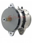
Regrettably, today the reg tripped on 14v ovco, haven't see that before. The inlet heater ran awhile, even with rapid warm up, bc it's effing cold. Of course, main volts were solid 24 on the gauge during that time bc my batts were maintained all night. On ign reset, main volts 28 solid, low volts are 16+ with the red flashing light. These regs seem to be either trash, or abused and resold as "almost new". This is the 2nd one. I believe we're spending allot of keyboard time troubleshooting systems that are fine expect for these regs. I'm not buying another one that's for sure. There's a nice brand new 150A 24v brushless alt from rare electrical in the shop that was promised to the track loader but it might get repurposed. "NEW 24V ALTERNATOR FITS CATERPILLAR J180 MOUNT 5101211223 1012109000 1012109001"
I though it was only a 100 but upon checking my receipt from ebay it's actually a 150. I have no clue how to adapt a J180 mount to this truck but I'm getting tired of the word "Neihoff"
 

Attachments

Lostchain

Well-known member
Steel Soldiers Supporter
284
586
93
Location
Portland, OR
Regrettably, today the reg tripped on 14v ovco, haven't see that before. The inlet heater ran awhile, even with rapid warm up, bc it's effing cold. Of course, main volts were solid 24 on the gauge during that time bc my batts were maintained all night. On ign reset, main volts 28 solid, low volts are 16+ with the red flashing light. These regs seem to be either trash, or abused and resold as "almost new". This is the 2nd one. I believe we're spending allot of keyboard time troubleshooting systems that are fine expect for these regs. I'm not buying another one that's for sure. There's a nice brand new 150A 24v brushless alt from rare electrical in the shop that was promised to the track loader but it might get repurposed. "NEW 24V ALTERNATOR FITS CATERPILLAR J180 MOUNT 5101211223 1012109000 1012109001"
I though it was only a 100 but upon checking my receipt from ebay it's actually a 150. I have no clue how to adapt a J180 mount to this truck but I'm getting tired of the word "Neihoff"
That’s a bummer man. I have an extra LMTV alternator bracket you’re welcome to if you need a foundation to fab up a custom mount. Also I’d be interested in buying your neihoffs off you if you’re giving up on them.
 
Top
AdBlock Detected

We get it, advertisements are annoying!

Sure, ad-blocking software does a great job at blocking ads, but it also blocks useful features of our website like our supporting vendors. Their ads help keep Steel Soldiers going. Please consider disabling your ad blockers for the site. Thanks!

I've Disabled AdBlock
No Thanks