• Steel Soldiers now has a few new forums, read more about it at: New Munitions Forums!

  • Microsoft MSN, Live, Hotmail, Outlook email users may not be receiving emails. We are working to resolve this issue. Please add support@steelsoldiers.com to your trusted contacts.

LMTV M1078 Tachometer

Juanri23

Member
35
2
8
Location
Spain
[QUOTE = "Awesomeness, publicación: 2222491, miembro: 45791"]
Hay dos modelos de alternador. El más antiguo, con el regulador de voltaje N3030, tiene el segundo terminal como sensor de campo, lo que no ayudará a impulsar un tacómetro. Los alternadores más nuevos tienen ese terminal como una línea de CA, que lo hará.
[/CITAR]
How do I connect the tachometer if I have the n3030?
 

mechanicjim

Member
90
40
18
Location
Chicago il
to get a Tach reading from the C.E.Niehoff Alternators/Regulators the Regulator needs to have a AC/P/R terminal. this termnal outputs a AC voltage that when connected to a proper tachmometer will output engine RPM. you can test this by putting you Mulitimeter to AC HZ setting while engine running and you should see alt RPM. so a reading like 210.0 Hz AC is 2100 Alt Rpm which is 700 Engine RPM(3 to 1 ratio). the early LMTV/FMTV with the N3030 don't have the AC terminal.
 

Juanri23

Member
35
2
8
Location
Spain
If I can use the bell sensor signal, I'll do that, just pulling cable to the cab and ready. I just wanted to know if there's a sensor I can take signal from.
 

Lifeson

New member
17
10
3
Location
italy
to get a Tach reading from the C.E.Niehoff Alternators/Regulators the Regulator needs to have a AC/P/R terminal. this termnal outputs a AC voltage that when connected to a proper tachmometer will output engine RPM. you can test this by putting you Mulitimeter to AC HZ setting while engine running and you should see alt RPM. so a reading like 210.0 Hz AC is 2100 Alt Rpm which is 700 Engine RPM(3 to 1 ratio). the early LMTV/FMTV with the N3030 don't have the AC terminal.
Which models of regulators have this configuration? Can they be replaced with n3030?
 

Reworked LMTV

Expedition Campers Limited, LLC
Supporting Vendor
1,506
1,174
113
Location
TN
Which models of regulators have this configuration? Can they be replaced with n3030?
The n3030 does not have an AC tap. Does not really matter though. You can always tap it before the rectifier or tap the bell housing sensor, as mentioned.
 

coachgeo

Well-known member
5,147
3,462
113
Location
North of Cincy OH
The n3030 does not have an AC tap. Does not really matter though. You can always tap it before the rectifier or tap the bell housing sensor, as mentioned.
what Reworked is eluding to here is the cost of a replacement regulator to get the AC output you want is so ENORMOUS it is a ridiculous means just to get the signal you want. Use one of the other resources mentioned in thread is far more logical.

that being said..... would still be good to know what regulators can replace what...... in case someone has a dead one ... and far all we know... you (Lifeson) happens to be one of them and thinking you might can kill two birds with one stone.
 

Lifeson

New member
17
10
3
Location
italy
The n3030 does not have an AC tap. Does not really matter though. You can always tap it before the rectifier or tap the bell housing sensor, as mentioned.
I connected the tachometer (ISSPRO R8530M the same one that Sean Fillner installed) to the PX26 (Frequency Divider) terminal where cables 3083 and 1444 from the Engine Speed Magnetic Pickup are connected but to no avail. I have however seen that the connections for the original tachometer (in the center of the dashboard) connect to terminals 1546-1550 from terminal P913 (?).
How can I get it to work?
 

Ronmar

Well-known member
3,845
7,474
113
Location
Port angeles wa
I connected the tachometer (ISSPRO R8530M the same one that Sean Fillner installed) to the PX26 (Frequency Divider) terminal where cables 3083 and 1444 from the Engine Speed Magnetic Pickup are connected but to no avail. I have however seen that the connections for the original tachometer (in the center of the dashboard) connect to terminals 1546-1550 from terminal P913 (?).
How can I get it to work?
Wire 1444 is the + signal from the sensor, and wire 3083 is the - signal from the magnetic pickup and is tied/referenced to ground at the freq divider connector. At the freq divider, wire 1444 is spliced to wire 1550 for the run over to the center dash Where it is also the + signal. I think the drawing may be wrong on specifying 1546 as the other wire/- signal in the center dash, as 1546 is 24V DC instrument power from CB 77.

That 24V DC power is fed to instrunments like oil pressure or engine temperature that feed it thru the meter coil then down to a pressure or temperature sensor that provide a varying resistance to ground based on the pressure or temperature sensed. This changes current flow thru the meter coil and the needle position To reflect what the sensor is seeing. The center tach does need power to function but for tack sense it should be looking at signal + and -(ground).

The engine RPM sensor is basically a small electric generator(coil of wire around a magnetic core). As the ring gear teeth pass in close proximity to the core a series of small voltage pulses are generated. If you connected the tach sense wires to this and 24V it would not work and might damage the tach or if 24V somehow got fed back thru the sensor which is tied to ground, it might burn up the pickup coil in the RPM sensor...

As for making yours work, my first question is do you have a signal coming from the RPM sensor? Since the sensor is a generator, you can check for this signal with a volt meter set for AC volts. At the freq divider, connect the meter leads to wire 1444 and 3083. With the engine running, see if you have any voltage there. I am not sure what the cat is supposed to be as I have not checked mine. the one on my tractor puts out 5 volts... If you do not see an AC voltage there, shut off the engine, unplug the freq divider connector and switch the meter to ohms and look for a circuit down thru the pickup on those same wires, 1444 to 3083. If you don’t have a circuit, check the connector at the sensor(drivers side bellhousing near the top and perform the same tests. The sensor coil should have 1440 ohms of resistance.

if you do have a voltage, it may be too weak. If the sensor has been unscrewed, the farther the head gets from the ring gear teeth the weaker the signal. What also sometimes happens is metal shavings from the ring gear collect on the magnetic head of the sensor and can disrupt/weaken the output. They also sometimes get loose and screw themselves in and the ring gear destroys the head of the sensor. You can unscrew it to check it and clean it. Before you unscrew it loosen the lock nut and see how far in it will turn before it touches the ring gear, then remove it to clean and inspect. screw it all the way back in till it touches, and then back it out 2 full turns... they are pretty simple, if they have proper resistance and are clean and positioned properly you should get AC voltage with the engine running.

if you get voltage at the sensor, but not when everything is plugged back in, it could also be the freq divider. It is not really a divider, it is an isolation amp, so STE can sample the sensor without loading it down so much that it won’t drive the installed tach... if it was shorted it might load the signal down.

The freq divider’s sole purpose is to feed STE, so you can simply remove it. You can also pull that black plastic box and the STE connector from under the dash. 3 connectors and it all comes right out...
 

INFChief

Well-known member
722
1,348
93
Location
New York
Attempting to revive the TACH issue - briefly.

I’ve got a A1. Have been thinking about adding a tach. My question is:

Does anyone know if the harnesses are different between the 0 & A1?

I would like to think that some the harnesses would not need modified and that the same harness could be used in all 1083 variants.

In The TM’s I’ve downloaded the -10 doesn’t discuss the 3126 engine. The 20 level TM’s have troubleshooting procedures for the tach.

It could very well be that the TM’s I have were superseded and I need to search for the Changes or entire manuals.

I prefer to research a bit before removing the dash, etc., to probe around.

This is an older thread and I was hoping someone has since explored the tach installation topic further.
 

Ronmar

Well-known member
3,845
7,474
113
Location
Port angeles wa
Attempting to revive the TACH issue - briefly.

I’ve got a A1. Have been thinking about adding a tach. My question is:

Does anyone know if the harnesses are different between the 0 & A1?

I would like to think that some the harnesses would not need modified and that the same harness could be used in all 1083 variants.

In The TM’s I’ve downloaded the -10 doesn’t discuss the 3126 engine. The 20 level TM’s have troubleshooting procedures for the tach.

It could very well be that the TM’s I have were superseded and I need to search for the Changes or entire manuals.

I prefer to research a bit before removing the dash, etc., to probe around.

This is an older thread and I was hoping someone has since explored the tach installation topic further.
Well the A1 with the 3126 engine, like all EFI engines has dedicated cam and crank sensors to generate RPM and timing info so the ECU can fire the injectors.

That RPM info from the ECU will be available on the data buss, I have seen OBD type tachometers, but not sure what would be required to use one on this data bus. Google ”adding a tach to a 3126“ haven’t looked, but I am sure you are not the first person to want to add a tach to a 3126…

Do you have a screw-in port for a flywheel Sensor? If so, It will probably be located on the bell housing near the top toward the drivers side. If it is there, I would look around on the nearby wiring harnesses to see if there are any tied back/capped electrical connectors. They may have kept the same tach system for the winch trucks and the wiring from that flywheel sensor point may be in place up to the center dash where the accessory panel was mounted… Wether the wire is there or not, If the sensor port is in the flywheel, you could add a magnetic pickoff/hall effect sensor to drive a tach and wire in the 2 wires yourself…
 

INFChief

Well-known member
722
1,348
93
Location
New York
Well the A1 with the 3126 engine, like all EFI engines has dedicated cam and crank sensors to generate RPM and timing info so the ECU can fire the injectors.

That RPM info from the ECU will be available on the data buss, I have seen OBD type tachometers, but not sure what would be required to use one on this data bus. Google ”adding a tach to a 3126“ haven’t looked, but I am sure you are not the first person to want to add a tach to a 3126…

Do you have a screw-in port for a flywheel Sensor? If so, It will probably be located on the bell housing near the top toward the drivers side. If it is there, I would look around on the nearby wiring harnesses to see if there are any tied back/capped electrical connectors. They may have kept the same tach system for the winch trucks and the wiring from that flywheel sensor point may be in place up to the center dash where the accessory panel was mounted… Wether the wire is there or not, If the sensor port is in the flywheel, you could add a magnetic pickoff/hall effect sensor to drive a tach and wire in the 2 wires yourself…
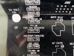
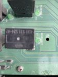
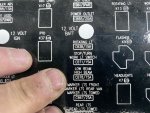
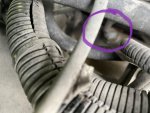
The port is there. I didn’t see the P connector the TM called for but I did see an unused P204. Cannot find that on any of the schematics either. I did a bit more troubleshooting reading to get an idea of the circuit and I looked up part #’s. I’ll look closer at the bundled wires near the flywheel housing tomorrow. I took Pictor the distribution power panel. C49E418C-5863-44DC-820A-0C91193F0FA4.jpegA2F2C710-A866-4833-8BD7-15EF38511E43.jpegB84E4AFD-58AE-433A-89DB-B863E3A88B19.jpeg
 

Attachments

Last edited:
Top