• Steel Soldiers now has a few new forums, read more about it at: New Munitions Forums!

  • Microsoft MSN, Live, Hotmail, Outlook email users may not be receiving emails. We are working to resolve this issue. Please add support@steelsoldiers.com to your trusted contacts.

M1008 alternator missing resistor

Wintergreen 86

New member
20
3
3
Location
kelowna, bc
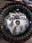
I just rebuilt the passenger alternator in my M1008 and it is still not charging. it gets excite voltage and has power at the the other connections (even though the gen 2 light doesn't come on). When re-reading the TMs and stickies i noticed my alt didn't have a resistor that others do. See images below.


Could this part be the issue? or should it work without it?

i put new bearings, diode trio, brushes and regulator in it. i plan to pull it back out and test each component but i thought i would ask about that resistor.
 

MarcusOReallyus

Well-known member
4,524
816
113
Location
Virginia
When re-reading the TMs and stickies i noticed my alt didn't have a resistor that others do.
Could this part be the issue? or should it work without it?


Well, either GM was in the habit of just throwing in random extra parts that aren't needed, or maybe, you need that part.
 

Tow4

Well-known member
Steel Soldiers Supporter
2,098
649
113
Location
Orlando, FL
I don't include the resistor in my kits because not all alternators have the resistor. If the resistor is there, it is reusable.

You can test the alternator on the vehicle with the engine running by connecting a wire from the B+ terminal on the alternator under test to the #1 regulator terminal (large wire in the regulator plug is the #1 terminal). Just unplug the regulator connector for the test. All the other wires from the vehicle need to be connected to the alternator.

If after testing you determine the alternator is not working, disassemble the alternator and check that the three screws that attach the regulator and brush holder assembly to the end casting are insulated and the insulators are not damaged. Make sure the wire that runs from the negative heat sink to the regulator is there.

If you have a DMM, you can check the trio. Put the black meter lead on the long trio terminal and the red lead on the short terminal. There should be continuity, there should be no continuity when you reverse the leads. The rectifier is tested the same way as the trio.

You can look at my rebuild thread (link in my signature) for pictures and details.
 

Wintergreen 86

New member
20
3
3
Location
kelowna, bc
I don't include the resistor in my kits because not all alternators have the resistor. If the resistor is there, it is reusable.

You can test the alternator on the vehicle with the engine running by connecting a wire from the B+ terminal on the alternator under test to the #1 regulator terminal (large wire in the regulator plug is the #1 terminal). Just unplug the regulator connector for the test. All the other wires from the vehicle need to be connected to the alternator.

If after testing you determine the alternator is not working, disassemble the alternator and check that the three screws that attach the regulator and brush holder assembly to the end casting are insulated and the insulators are not damaged. Make sure the wire that runs from the negative heat sink to the regulator is there.

If you have a DMM, you can check the trio. Put the black meter lead on the long trio terminal and the red lead on the short terminal. There should be continuity, there should be no continuity when you reverse the leads. The rectifier is tested the same way as the trio.

You can look at my rebuild thread (link in my signature) for pictures and details.
Mine did not have the resistor, but otherwise appears to be a standard unit. It has been rebuilt before so it is possible it had been removed for some reason. the kit i got didnt have new one, but i can order one if needed.

I have seen your rebuild thread, thanks it was helpful.

I am aware of the test procedures and plan to pull the alt apart and do them. i had just assumed the new parts were good, but of course that isn't always the case.
 

Tow4

Well-known member
Steel Soldiers Supporter
2,098
649
113
Location
Orlando, FL
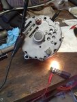
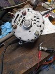
The light should come on if everything is connected properly. You can make a test light if you don't have one to easily test your alternator on the truck. Hook it up as shown below.

This is a Delco 10SI alternator that I converted to isolated ground. This alternator has the same regulator that I sell in my kits. I did not install a resistor or capacitor as they were not required for my application.

Here you can see the internal regulator connections. Note the ground wire running from the rectifier NHS to the regulator. This is required because the regulator is not grounded to the end casting in an isolated ground alternator the way it is normally in a negative ground alternator.

IMG_20190304_115245101.jpg


This test shows the light will turn with the B- attached to the negative terminal on the alternator and the B+ attached to the bulb center contact and the bulb ground is connected to the regulator #1 terminal.

IMG_20190304_120856244.jpg


If the internal ground wire from the rectifier NHS to the regulator is missing or the alternator is only grounded at the case, the light will not turn on and the alternator will not work.

IMG_20190304_121027852.jpg
 

Wintergreen 86

New member
20
3
3
Location
kelowna, bc
thanks for the help tow4. all the checks i ran seem to indicate the alternator still has a problem. i think it is the rotor as one of the slip rings seems to be shorting to the shaft. the resistance is really high at about 25-30 megaohms, but still a short. I ordered up a rebuilt 27si 100 amp remy alt from rock auto and i will swap the back of the case out and convert it to isolated ground.

Part number is 20136 and is $95 Canadian including core charge (so like 70 bucks USD). can be found listed for 70s big block caddys, late 70s buick estate wagons and even big block 2wd suburbans up to 82. probably many more. if it doesnt work ill report back.
 

Wintergreen 86

New member
20
3
3
Location
kelowna, bc
Had a suspicion last night and sure enough found something else this morning. The 'ground' wire is getting 24 volt not 12. Guess I focused to much on the excite wire and not exactly what voltage the other connections had.

I'll have to trace the wire and see where it is connected. The glow plugs have been converted to 12v (resistor/ ballast deleted). So the wiring has been messed with a bit.
 
Top
AdBlock Detected

We get it, advertisements are annoying!

Sure, ad-blocking software does a great job at blocking ads, but it also blocks useful features of our website like our supporting vendors. Their ads help keep Steel Soldiers going. Please consider disabling your ad blockers for the site. Thanks!

I've Disabled AdBlock
No Thanks